
buzzer circuit

The NE555 timer IC is configured in an astable mode, allowing it to function as an oscillator that generates a square wave output. In this configuration, the frequency of the oscillation is determined by the resistors and capacitors connected to the timer. The 1K variable resistor serves as a means to fine-tune the frequency, while the 15K resistor sets a baseline resistance that contributes to the timing cycle.
To implement this circuit, the following connections are essential: pin 1 (ground) is connected to the negative terminal of the power supply, while pin 8 (VCC) is connected to the positive terminal of the 9-volt supply. Pins 2 (trigger) and 6 (threshold) are interconnected, and pin 2 is also connected to the junction of the 1K variable resistor and the 15K resistor, which are arranged in series with the capacitor connected to pin 6. The capacitor, typically a non-polarized type, is connected between pin 6 and ground, influencing the timing characteristics of the output.
Pin 3 (output) is connected to the positive terminal of the speaker, while the negative terminal of the speaker is grounded. The output from the NE555 will drive the speaker, producing the desired buzzer sound. To ensure reliable operation, it is advisable to use electrolytic capacitors rated for at least 10 volts to prevent damage from voltage spikes. The choice of speaker impedance between 8 to 25 ohms will affect the loudness and quality of the sound produced.
This circuit can be further enhanced by integrating additional components, such as diodes for protection against back EMF generated by the speaker, or additional resistors and capacitors to modify the sound characteristics. Other configurations, such as the 555 tone generator and siren circuit, can also be explored for varied audio output applications.This is a project of a 555 buzzer circuit. NE555 is a timer IC comes in 8 pin dip package, it performs wide variety of tasks in electronic circuits. The circuit mentioned below will produce a buzzer sound when 9 volt power will be applied. The frequency of sound can be changed with the help of 1K variable resistor and changing the value of 15K res
istor. All electrolytic capacitors will be of 10 volt ratings, use 8 to 25 ohms speaker. There are also other circuits which you can use for buzzer purpose like 555 tone generator and siren circuit. 🔗 External reference
Related Circuits
The following circuit illustrates the sensor circuit of an analog line follower robot. Features include control by a microcontroller and a sensor circuit. The sensor circuit for an analog line follower robot is designed to detect the presence of a...
Operating radio transmitters without a license is illegal in most countries, so caution is advised with transmitter circuits. This FM low-power circuit is designed to operate within the 87-108 MHz band II, providing a range of approximately 20 to...
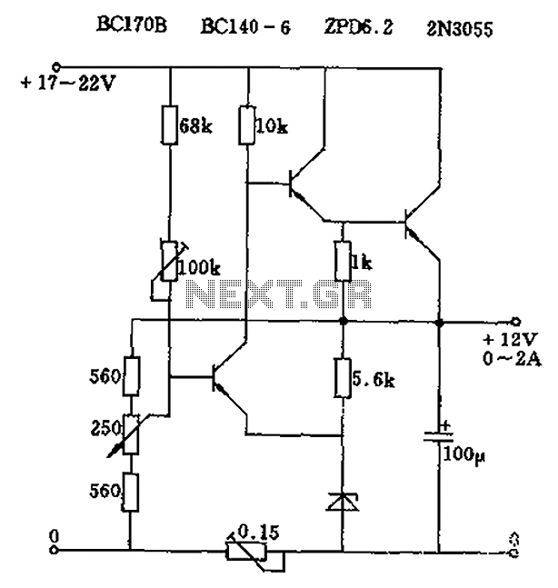
The circuit output voltage can be continuously adjusted from zero to its maximum value. The baseline is established by a constant current sourced from the auxiliary power supply circuit. The reference current of 500 microamperes can be fine-tuned to...
This project involves a simple circuit designed to mix two or more audio channels into a single channel, such as converting stereo audio into mono. The circuit is capable of accommodating multiple input channels while maintaining low power consumption....
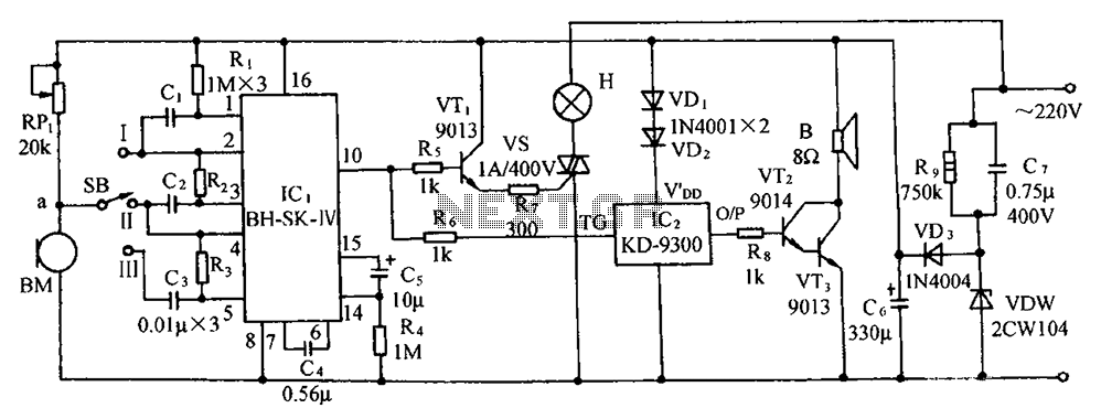
The circuit includes a microphone transducer, voice circuits, an SCR control circuit, a vocal music buck rectifier circuit, and an AC circuit. The BH-SK-IV serves as the core of the device. The described circuit is a complex assembly designed to...
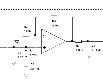
A problem has been encountered in a Phase-Locked Loop (PLL). A loop filter has been utilized, but the output spectrum does not meet expectations. In a Phase-Locked Loop (PLL) system, the loop filter plays a crucial role in determining the...