
Two Speed Contactor DC Motor Controller

The contactor controller described utilizes a straightforward design that leverages mechanical relays to control the power supplied to a motor, making it suitable for applications such as electric scooters. The core components include three 12V relays, which serve as switches to connect or disconnect the motor from the power source. The relays are activated by the two switches, allowing the user to select between different operational modes.
In this configuration, when the relays are arranged to connect the batteries in parallel, the system provides a lower voltage but higher current output, which is ideal for slow-speed operation. Conversely, when the relays switch to connect the batteries in series, the voltage doubles, providing higher speed to the motor. This dual functionality is achieved without the complexity of electronic speed controllers, making the design robust and reliable, as it avoids potential failure points associated with semiconductor components.
The use of two 12V batteries ensures that the system can maintain a balanced discharge rate, extending battery life and efficiency. When the motor is not in use, the batteries are configured in parallel, allowing for easy recharging without requiring complex circuitry. This design choice not only simplifies the overall system but also enhances user safety and maintenance ease.
To implement this circuit, careful consideration must be given to the relay specifications, ensuring they can handle the current and voltage requirements of the motor. Additionally, the switches should be rated appropriately to handle the load and provide a reliable interface for the user. Overall, the contactor controller is an effective solution for controlling motor speed in electric vehicles, emphasizing simplicity and reliability.The simplest of all motor controllers (besides a straight on/off switch) is the contactor controller. Aaron designed this contactor controller for use in his electric scooter project . It is based around three 12V relays, two 12V batteries, two switches and of course a motor. Having no silicon to "fry", it is quite reliable and robust. A contactor controller works by rearranging the two (or more) supply batteries between series and parallel.
This gives the motor a slow speed (batteries in parallel, current adds) and a fast speed (batteries in series, voltage adds). This assures that both batteries are discharged equally. When the circuit is "at rest", the batteries are connected in parallel, which allows easy recharging.
🔗 External reference
Related Circuits
The circuit diagram represents a brushless DC motor driving circuit designed for a 45V/8A application. It features an open voltage-controlled design that allows for speed adjustment through an external potentiometer connected to a PWM duty cycle. The diagram illustrates...
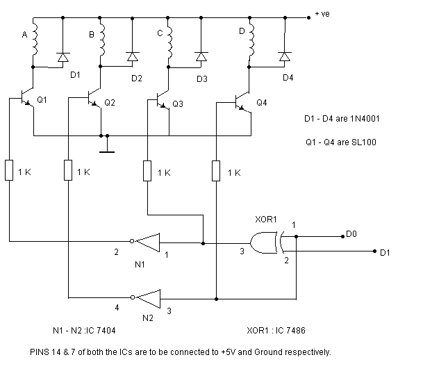
The circuit shown above can be used to control a unipolar stepper motor which has FOUR coils. The above circuit can be for a motor current of up to about 500mA per winding with suitable heat sinks for the...
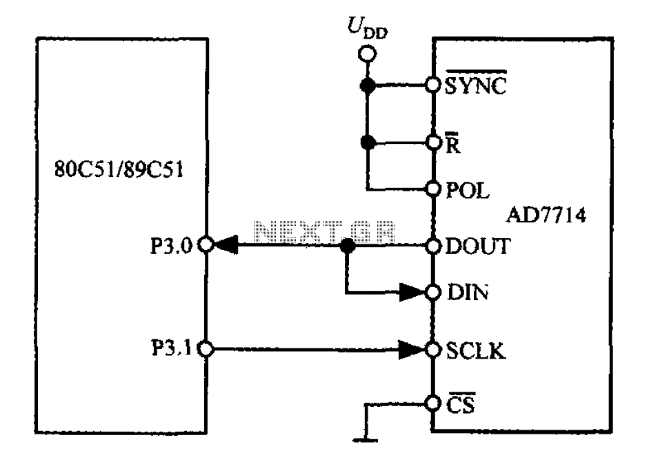
The 3-wire interface to the AD7714 can be utilized with various microcontrollers, including microcontrollers and microprocessors. This 3-wire serial interface is particularly suitable for isolation systems, allowing the use of optical couplers. The interface circuit between the AD7714 and...

The PWR-DRV1 from Power Integrations is a single chip that creates a "bang-bang" controller capable of switching 275 mA and operates from the rectified 115-Vac mains. An on-chip zener diode provides power to the chip from high voltage via...
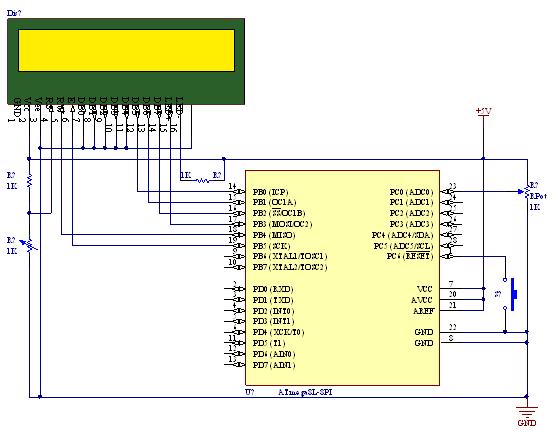
A straightforward tutorial on utilizing the ADC (Analog to Digital Converter) unit of the AVR microcontroller, demonstrated with the Atmega8, including a circuit diagram and code examples. The ADC unit in the Atmega8 microcontroller is a crucial component that allows...
The ATA5423, ATA5425, ATA5428, and ATA5429 are highly integrated UHF ASK/FSK multi-channel half-duplex transceivers characterized by low power consumption. These devices are housed in a compact 7 x 7 mm QFN48 package. The receiving section features a fully integrated...