
CW signal processor

The described circuit focuses on enhancing the performance of a Continuous Wave (CW) transmission system by implementing a phase-locked loop (PLL) configuration. The 567 PLL is adept at locking onto specific frequency tones, in this case, those within the 500 to 1100 Hz range, which are typical for CW operations. This capability is crucial for filtering out unwanted noise and ensuring that the desired signal is accurately processed.
The integration of a Schmitt trigger plays a vital role in stabilizing the output of the PLL. It provides hysteresis, which helps to prevent false triggering by ensuring that the output does not fluctuate due to minor variations in the input signal level. This characteristic is particularly important in audio applications where the PLL output could otherwise remain low even after the audio signal has ceased, potentially leading to undesired behavior in subsequent circuit stages.
The activation threshold of 10 to 15 millivolts for the audio input indicates a sensitivity that allows the circuit to respond to relatively weak signals, making it effective in environments with low audio levels. This feature is beneficial for operators who may be working in conditions where signal strength is variable.
The automatic switching feature of circuit B enhances the usability of the system by ensuring that the operator has continuous access to live audio input, even in the event of a signal loss. The inclusion of a delay before switching back to live audio prevents abrupt transitions that could disrupt the operator's workflow. The design accommodates different relay coil voltages, providing flexibility in implementation. By allowing the circuit to be powered from a +12 volts supply, it broadens the range of compatible components and simplifies integration into existing systems.
In summary, this circuit serves a critical function in CW operations by providing interference rejection, signal stabilization, and reliable switching capabilities, thereby enhancing the overall performance and user experience of the system.This circuit provides interferenced rejection for the CW operator. The 567 phase-locked loop is configured to respond to tones from 500 to 1100 Hz. The Schmitt trigger reduces the weighting effect caused by the output of the PLL remaining low after removal of the audio signal. Ten to 15 millivolts of audio activate the circuit For periods of loss of signal, circuit B will automatically switch back to live receiver audio after a suitable delay. (If a relay with a 5-volt coil is not available, the circuit can also be powered from +12 volts) When circuit B is used, the contacts on relay K1 replace SI.
Related Circuits
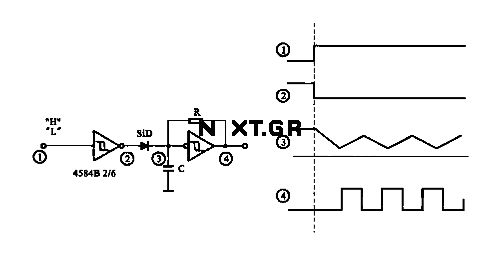
The circuit generates a controlled pulse signal. When a high pulse signal is applied to the input terminal O (start), the output pulse signal is activated. Conversely, when a low signal is received at the input terminal O (stop),...
This LED (Light Emitting Diode) display consists of 10 LEDs to indicate the level of an input signal. If the signal is low, only LED #1 will light up. As the signal level increases, the illuminated dot will progress...
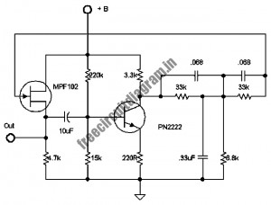
The following circuit illustrates a stable 60 Hz frequency signal generator circuit diagram. Features include a 0.068 µF capacitor incorporated within a feedback loop, allowing for DC-to-AC conversion. This circuit is designed to generate a stable 60 Hz sine wave...
This is a PIN diode-based RF signal attenuator circuit that operates with input frequencies ranging from 1 MHz to 500 MHz. PIN diodes are among the most commonly used components in RF applications. The RF signal attenuator circuit utilizing PIN...
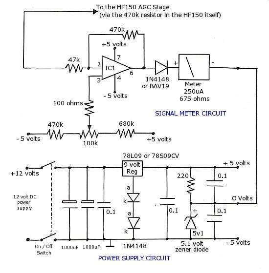
The operational amplifier (op-amp) used in the signal meter circuit is the TL061. The LF351 can also be used interchangeably, as it has the same pin layout. For those using a TL062 or similar models, the differing pin configurations...
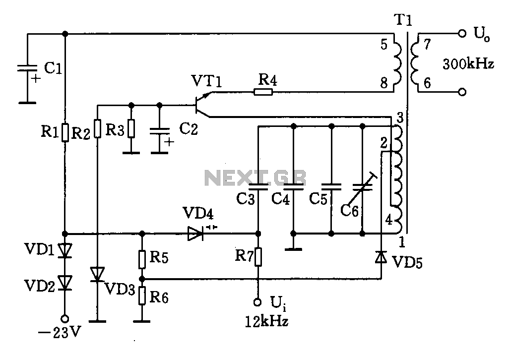
This circuit is designed for a 300 kHz signal generator. It includes components such as VT1, T1, VD4, and other associated elements. The voltage-controlled oscillator (VCO) employs an LC-tuned collector, with VT1 functioning as the oscillating transistor, varactor diode...