
300kHz signal generator circuit
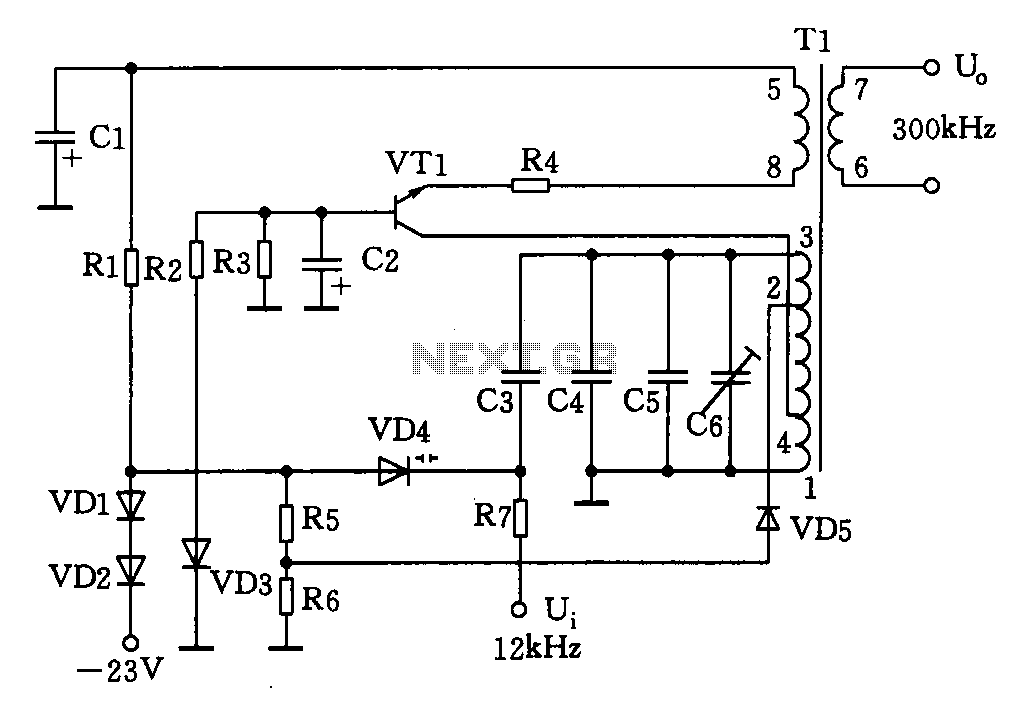
Component selection includes: Transistor VT1: 3DG6C, with a gain range of 65 to 85; Diodes VD1, VD2: 2CPl4; VD5: 2CK18; Zener diode VD3: 2CWl4; Variable capacitance diode VD4: 2CC5. Resistors are specified as R1: 3.6k, R2: 3.3k, R3: 5.1k, R4: 510Ω, R5: 3.9k, R6: 3k, R7: 100k, with models RTX-0.125W. Capacitors include C1, C2: 5 µF 30V; C3: 51 pF 100V; C4: 820 pF 100V; C5: optional; C6: 20 pF. The variable filter T1 is of model L22, with an inductance of A = 100. Windings L1-4 use 0.29 mm wire, with approximately 27 turns for L1-3, 18 turns for L2-3, 9 turns for L4-2, 7 turns for L5-8, and 6 turns for L6-7. The total inductance for L1-3 is 292 µH, with a tolerance range of 0 to 10 µH.
The 300 kHz signal generator operates by utilizing a varactor diode (VD4) to modulate the capacitance in response to a negative control voltage. This modulation allows fine-tuning of the oscillation frequency, which is critical for applications requiring precise signal generation. The oscillator circuit's stability is enhanced by the Zener diode (VD3), which regulates the voltage to maintain consistent performance across varying conditions.
The inductive components, particularly the transformer T1, play a crucial role in the signal generation process. The specified winding configurations and wire gauges are designed to optimize performance while minimizing losses. The selection of high-quality capacitors and resistors ensures reliability and accuracy, which are essential for generating a stable 300 kHz signal.
In summary, this circuit design integrates a variety of components to achieve effective signal generation with adjustable frequency characteristics, making it suitable for various electronic applications where precise oscillation is required.Shown for the 300kHz signal generator. It consists VT1, T1, VD4 composition VCO and associated components. VCO using LC tuned collector, VTl the oscillating tube, varactor diode VD4, T1 1-3 inductive winding capacitance C3 ~ C6 and variable tuning circuit composed varactor VD4 anti-bias work from a negative voltage is applied to the control terminal, to change its capacitance. An oscillation signal output from the winding Tl 6-7. Wherein, C6 is the frequency tuning capacitor. VD3 stable oscillator stage operating voltage, stable voltage of 6.8V 0.2V.Component selection: Transistor VT1: 3DG6C, = 65 ~ 85.
Diodes VD1, VD2: 2CPl4, VD5: 2CK18. Zener diode VD3: 2CWl4. Variable capacitance diode VD4: 2CC5. Resistance R1: 3.6k, R2: 3.3k, R3: 5.1k, R4: 510, R5: 3.9k, R6: 3k, R7: 100k, which models are RTX-0.125W. Capacitors Cl, C2: 5 F30V, C3: 51pFl00V, C4: 820pFl00V, when commissioning C5 :( optional), C6: 20pF.
Variable filter T1: Model L22, A = 100. L1-4: µ0.29mm, around the 27-turn, L2-3: µ0.29mm, turns around l8, L4-2: µ0.29ram, around 9 turns, L5-8: µ0.29mm, around 7 turns, L6- 7: µO. 29mm, about 6 turns. L1-3 = 292 H, tolerance range: 0 ~ 10 H.
Related Circuits
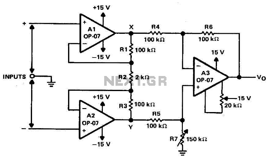
Operational amplifiers A1 and A2 are connected in a non-inverting configuration to form amplifier A3. The operational amplifier A3 can be classified as a subtractor circuit that converts the differential signal between the floating points X and Y into...
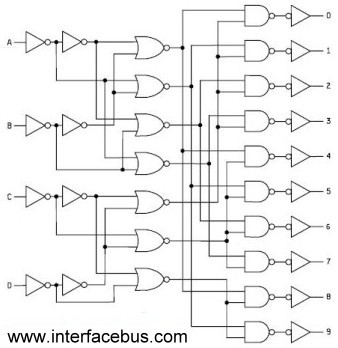
Binary Coded Decimal (BCD) is a number system that counts from 0 to 9 and then repeats. The table below illustrates the conversion between different numbering systems and BCD code. BCD is also known as 8421 because the least...
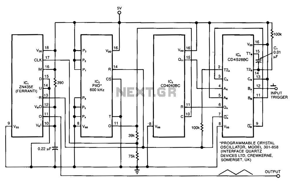
The ramp generator serves as a cost-effective alternative to commercial function generators, offering a more linear and repeatable output compared to traditional analog integrators. This circuit produces a triangle waveform in burst mode, generating two cycles of 10.24 ms...
The diagram illustrates the principle circuit of a radio control car receiver. Important notes include the selection of transistor Q1, which is specified as either 1815 or 9018, along with the bias resistor R1, which has values of 240K...
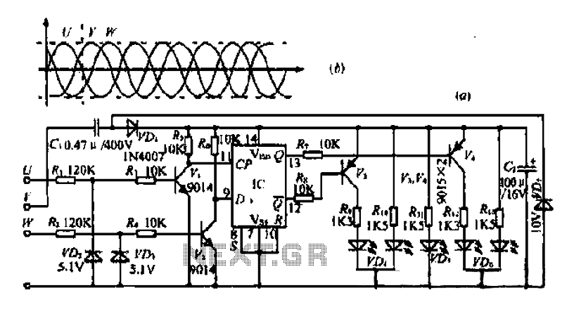
The three-phase voltage waveform diagram illustrates that when one phase voltage transitions from positive to negative across the zero point, the subsequent phase voltage becomes positive while the third phase remains negative. The U terminal voltage is positive when...
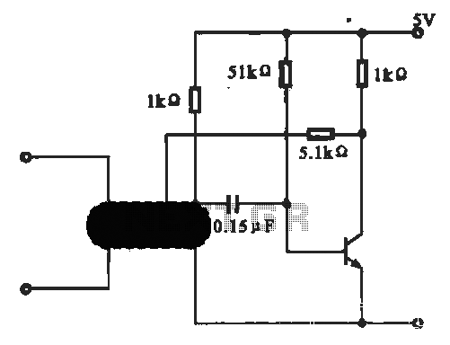
This circuit illustrates an oscillator that is controlled by an optocoupler, utilizing photoelectric coupling to drive a transistor. The oscillator circuit described operates by employing an optocoupler to provide electrical isolation between its input and output stages while allowing control...
Warning: include(partials/cookie-banner.php): Failed to open stream: Permission denied in /var/www/html/nextgr/view-circuit.php on line 713
Warning: include(): Failed opening 'partials/cookie-banner.php' for inclusion (include_path='.:/usr/share/php') in /var/www/html/nextgr/view-circuit.php on line 713