
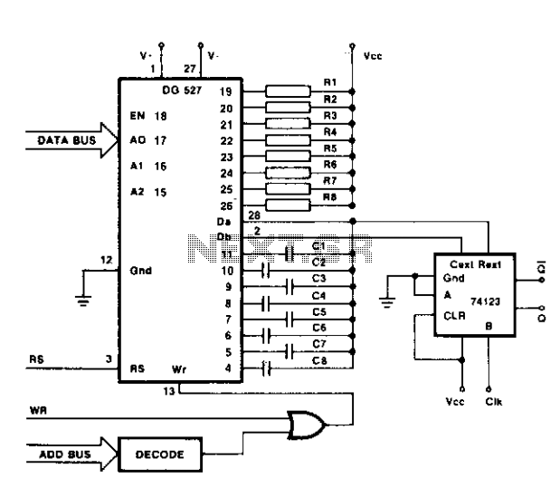
Controlled pulse signal generating circuit

This pulse signal generating circuit operates based on a simple yet effective design that utilizes a combination of digital logic components, such as flip-flops, resistors, and capacitors. The circuit's primary function is to produce a square wave output signal that can be controlled through an input signal.
When the input terminal O receives a high signal, it triggers a flip-flop, which changes its state and allows current to flow through the output stage. This transition generates a pulse output, which can be used for various applications, such as timing circuits, frequency modulation, or as a clock signal for other digital circuits. The duration and frequency of the output pulse can be adjusted by modifying the values of the resistors and capacitors in the timing circuit.
Upon receiving a low signal at the input terminal O, the flip-flop resets to its initial state, cutting off the current flow and halting the output pulse. This feature allows for precise control over the timing of the output signal, making it suitable for applications that require on-demand pulse generation.
The design can be further enhanced by incorporating additional components such as diodes for signal conditioning or transistors for driving higher loads, depending on the requirements of the specific application. Additionally, integrating a microcontroller can provide programmable control over the pulse width and frequency, expanding the circuit's functionality and adaptability in various electronic systems.Controlled pulse signal generating circuit FIG controllable pulse signal generating circuit, when the input terminal O start (start) pulse signal (input high), electric road be gan work output pulse signal; when O stop signal input terminal (low level), the circuit stop working, no pulse signal output.
Related Circuits
For many applications, it is necessary to delay signals. Consider applications in automation and control systems. A signal delay circuit can be established using two monoflops. Signal delay circuits play a crucial role in various electronic applications, particularly in automation...
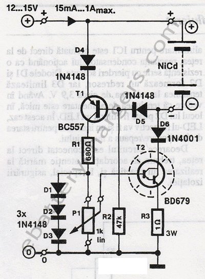
This 24V to 36V linear battery charger is long overdue. While this is an old circuit technique, it is optimized for charging higher voltage lead-acid batteries. The 24V to 36V linear battery charger is designed to provide a stable charging...
This HD TV UHF wideband amplifier (Ultra High Frequency amplifier) provides a total gain of 10 to 15 dB within the frequency range of 400 to 850 MHz, making it suitable for areas with weak television signals. To ensure...
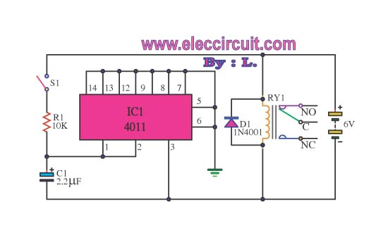
This circuit illustrates the use of the 4011 integrated circuit (IC) for a surge protection electronic circuit diagram. Features include the ability to delay the activation of other appliances connected to the output. The 4011 IC is a quad 2-input...
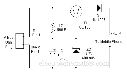
A mobile phone can be charged using the USB outlet of a PC. This simple USB cellphone charger circuit provides a regulated output of 4.7 volts for charging the mobile phone. The USB outlet typically supplies 5 volts DC...
Differential multiplexers are typically employed in process control applications to mitigate errors caused by common mode signals. In this circuit, the dual multiplexing capability of the switch is utilized. This is accomplished by using the multiplexer to select pairs...