
dancing lights circuit diagram

The described circuit utilizes two astable multivibrators to create a visually engaging display of LED lights that can be customized for various applications, such as decorative lighting or indicators. The first multivibrator, composed of transistors T1 and T2, generates a continuous square wave output that drives one set of LEDs. The second multivibrator, utilizing transistors T3 and T4, functions similarly to control a different set of LEDs or to create a combined effect with the first set.
The duty cycle of each multivibrator is critical in determining the on-off timing of the LEDs. By varying the resistance and capacitance values in the RC time constant, the flashing speed and pattern can be fine-tuned. Potentiometers VR1 and VR2 allow for manual adjustment, providing flexibility in the design. When light-dependent resistors are used in place of potentiometers, the circuit becomes responsive to environmental light levels, creating a dynamic interaction between the LEDs and their surroundings.
The total cost of the circuit is estimated at Rs 30, making it an economical choice for hobbyists and DIY enthusiasts. The arrangement of colored LEDs can be designed in various configurations to enhance the visual impact of the display. It is important to consider that the performance and patterns generated by the circuit may vary based on the specific components used and their arrangement.
This circuit provides an excellent platform for experimentation with basic electronic components and concepts, allowing users to explore the principles of multivibrator operation and light modulation while creating an eye-catching display.Here is a simple circuit which can be used for decoration purposes or as an indicator. Flashing or dancing speed of LEDs can be adjusted and various dancing patterns of lights can be formed. The circuit consists of two astable multivibrators. One multivibrator is formed by transistors T1 and T2 while the other astable multivibrator is formed by T3
and T4. Duty cycle of each multivibrator can be varied by changing RC time constant. This can be done through potentiometers VR1 and VR2 to produce different dancing pattern of LEDs. Total cost of this circuit is of the order of Rs 30 only. Potentiometers can be replaced by light dependent resistors so that dancing of LEDs will depend upon the surrounding light intensity. The colour LEDs may be arranged as shown in the Figure Disclaimer: All the information present on this site are for personal use only.
No commercial use is permitted without the prior permission from authors of this website. All content on this site is provided as is and without any guarantee on any kind, implied or otherwise. We cannot be held responsible for any errors, omissions, or damages arising out of use of information available on this web site.
The content in this site may contain COPYRIGHTED information and should not be reproduced in any way without prior permission from the authors. 🔗 External reference
Related Circuits
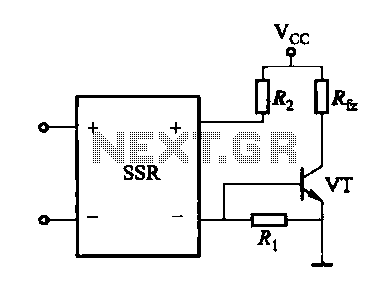
A DC solid-state relay (DC-SSR) driving a high-power load circuit is illustrated in diagram (a) below; the high-power load driving circuit is depicted in diagram (b) below. The DC solid-state relay (DC-SSR) serves as a crucial component in controlling high-power...
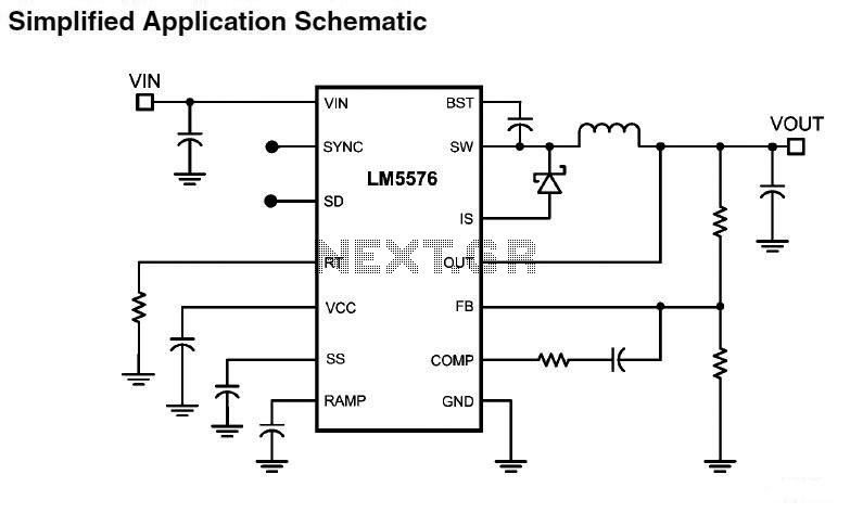
LM5576MHX absolute maximum ratings: (1) VIN to GND: 76V; (2) BST to GND: 90V; (3) PRE to GND: 76V; (4) SW to GND (Steady State): -1.5V; (5) BST to VCC: 76V; (6) SD, VCC to GND: 14V; (7) BST...
Working with lasers can be enjoyable and intriguing, but it can also be costly. High voltage power supplies for laser tubes are often more expensive than the tubes themselves. However, this power supply can be constructed using common components...
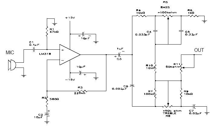
This simple microphone preamplifier is based on the LM318 operational amplifier. The LM318 operates as a standard non-inverting amplifier. Resistor R1 provides a ground input path for the bias current of the non-inverting input. The combination of R2 and...
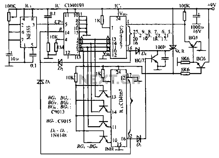
The circuit consists of an oscillator, a counter, and an Iseki circuit divided into three parts. The oscillator is based on the NE555 timer and several external RC components, generating a pulse signal for the counter. The instantaneous power...
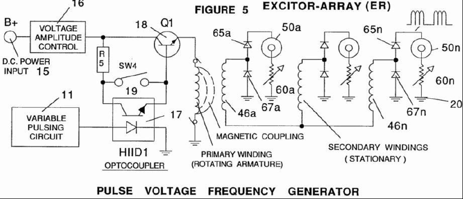
A power supply system utilizes a generator as a source of fuel to separate hydrogen and oxygen gases from natural water. It has the capability to control gas production by varying the amplitude of the voltage and/or the pulse...