
LM318 microphone preamplifier circuit design

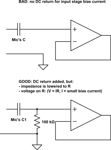
The microphone preamplifier circuit features the LM318 operational amplifier configured in a non-inverting arrangement, which is ideal for amplifying low-level audio signals from microphones. The inclusion of resistor R1 is critical as it establishes a DC path to ground for the bias current, ensuring stable operation of the non-inverting input.
The frequency response of the circuit is shaped by the components R2 and C2, which form a high-pass filter that effectively attenuates frequencies below 30 Hz. This design choice helps eliminate unwanted low-frequency noise, providing a cleaner audio signal. The gain of the amplifier is set to approximately 50 dB, achieved through the resistor ratio of R3 to R2. This gain ensures that the output signal is sufficiently amplified for further processing or mixing.
R3 plays a vital role in maintaining stability and linearity within the amplifier by providing negative feedback from the output back to the inverting input. This feedback mechanism is essential for minimizing distortion and enhancing the fidelity of the audio signal.
Capacitor C3 serves as an AC coupling component, allowing the amplified audio signal to pass while blocking any DC offset that could interfere with subsequent audio processing stages, such as tone control. The tone control section is bifurcated into bass and treble controls, with the upper half dedicated to adjusting low-frequency response and the lower half focusing on high frequencies. The use of audio taper potentiometers (R5 and R8) allows for more intuitive control over the tonal characteristics of the audio signal, providing smoother adjustments at lower levels of rotation.
Finally, the output section incorporates a 50 k ohm potentiometer, which allows for fine-tuning of the overall output level or gain of the preamplifier. This feature is particularly useful in live sound applications or recording environments where precise control over signal levels is necessary to prevent distortion or clipping in subsequent audio stages. Overall, this microphone preamplifier circuit is designed to deliver high-quality audio amplification with customizable tonal shaping capabilities.This simple microphone preamplifier is based on the LM318 op amp. The LM318 op amp is operated as a standard non-inverting amplifier. Resistor R1 provides an input path to ground for the bias current of the non-inverting input. The combination of R2 and C2 provides a frequency roll-off below 30 Hz. At 30 Hz and above the gain is relatively flat a t about 50 dB, set by the ratio R3/R2. R3 furnishes negative feedback from the output to the inverting input of the op amp. C3 ac couples the preamp to the tone control section. The top half of the tone control section is the bass control. The bottom half controls the treble frequency response. These tone controls (R5 and R8) require audio taper (logarithmic) potentiometers. The 50 k ohm potentiometer on the output can be used to set the output or gain of the preamp. 🔗 External reference
Related Circuits
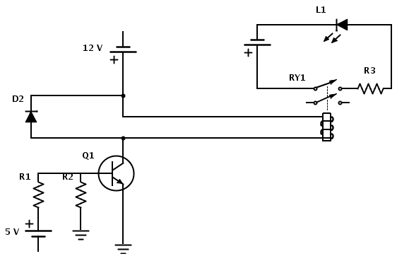
Create a circuit that enables the activation of a relay to control an LED. The relay operates at 12 V, while the available input voltage is 5 V. An NPN transistor will be utilized to switch the power to...
Several KE 4-211-2 Sennheiser microphones were utilized to create a device for acoustic signal analysis. These microphones are connected to a National Instruments data acquisition device via approximately 1 meter long cables, with a sampling rate set at 50...
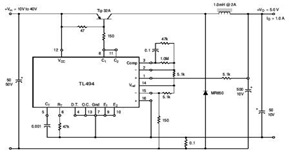
The circuit illustrates a TL494 pulse width modulated step-down converter schematic. This circuit allows for testing of line regulation, load regulation, output ripple, short circuit current, and efficiency under various input voltage conditions. A detailed table of these tests...
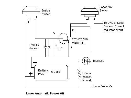
Here is the automatic laser power-off circuit schematic. This circuit features a visible power indication. In this case, the ground is connected on one side. The automatic laser power-off circuit is designed to enhance safety and efficiency in laser applications...
This circuit can manage nine independent telephones using a single telephone line pair located at nine different locations. It functions as a bidirectional telephone line simulator without the need for actual telephone lines, allowing for coupling, testing, and demonstration...
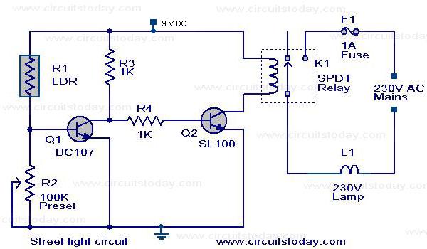
The circuit diagram of an Automatic Street Light Controller Circuit is explained in this post. The Automatic Street Light Controller Circuit is designed to automatically turn on street lights at dusk and turn them off at dawn. This functionality is...