
Dark-Activated Alarm With Pulsed Tone Output Circuit

The circuit utilizes two NOR gates (A and B) to generate a low-frequency oscillation. Under conditions of low light, the CDS (Cadmium Sulfide) cell reduces its resistance, effectively sending a logic low signal to NOR gate A. This condition activates the low-frequency oscillator, which produces a square wave signal at a frequency of 10 Hz. The output from this oscillator serves as a control signal to enable the high-frequency oscillator formed by NOR gates C and D.
The high-frequency oscillator operates at a frequency of around 1000 Hz, which can be influenced by the configuration and values of the resistors connected to the circuit. Resistor R1 plays a crucial role in determining the pulse rate of the low-frequency oscillator; by varying its resistance, the timing characteristics of the oscillation can be adjusted, allowing for a customizable output frequency.
Resistor R2 is used to modify the tone of the output signal, providing further versatility in the application of the circuit. The tone can be altered based on the resistance value chosen for R2, which affects the waveform characteristics as it passes through the high-frequency oscillator.
Additionally, resistor R3 is integral in establishing the trigger point for the oscillation. It sets the threshold level at which the circuit transitions from one state to another, ensuring reliable operation of the oscillators. The careful selection of these resistors allows for fine-tuning of the circuit's performance, making it suitable for various applications where sound generation or signal modulation is required. Overall, this configuration provides a robust and adjustable solution for generating oscillatory signals in electronic applications. NOR gates a and b form a low-frequency oscillator that is activated when the CDS cell, under dark conditions, causes NOR gate a to see a logic zero at one input. This low-frequency (10 Hz) gates a high-frequency oscillator (c and d) to oscillate at around 1000 Hz.
Rl can be varied to change the pulse rate and R2 to change the tone. R3 sets the trigger point.
Related Circuits
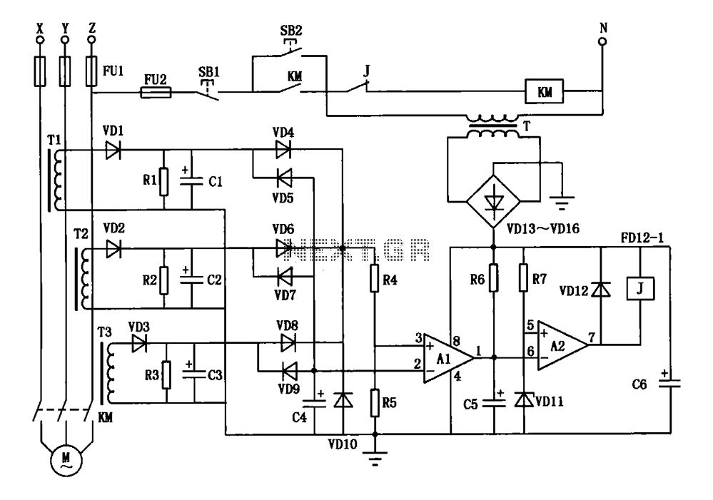
A current three-phase motor phase protection circuit is designed to detect three-phase current using homemade small current transformers T1, T2, and T3. The current signals are collected by rectifiers VD1, VD2, and VD3, while capacitors C1, C2, and C3...
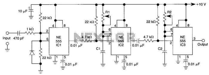
Three 555 IC timers are utilized in this circuit to create a simple delayed-pulse generator. IC1 functions as a waveform shaper to generate a rectangular waveform. IC2 generates a delaying pulse that triggers IC3 on the trailing edge of...
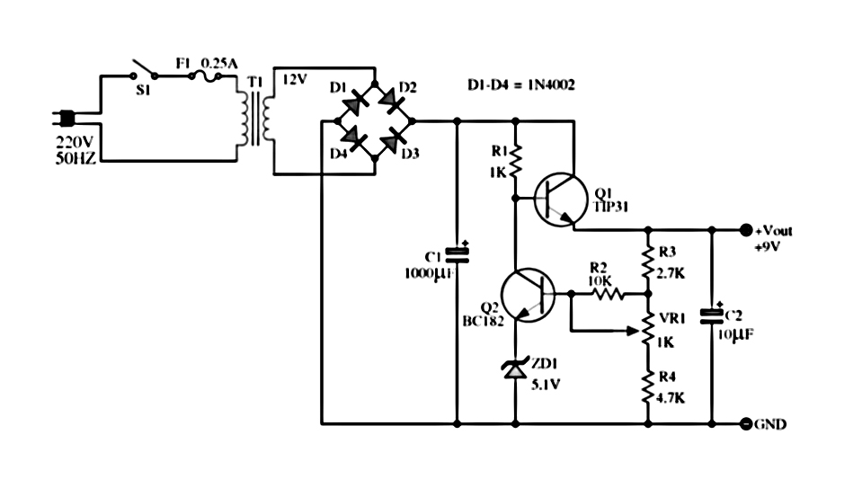
The power supply described utilizes a regulator composed of two NPN transistors. One transistor functions as the power regulator, while the other controls the output voltage. This power supply offers an adjustable output voltage range of 6-12 VDC. The...
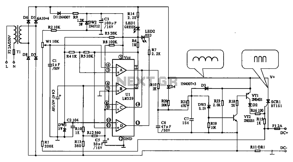
The Chizuru 100Hz channel frequency pulse charging circuit for electric bike batteries is designed to manage the charging process efficiently. It features a step-down transformer (Tl) and a bridge rectifier formed by diodes D5 to D8. The output ripple...
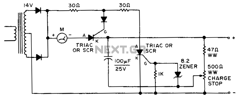
By adjusting the circuit with a 500-ohm resistor, the resistor is integrated into a fully charged battery system. The circuit described involves a 500-ohm resistor that plays a crucial role in regulating the operation of a fully charged battery system....
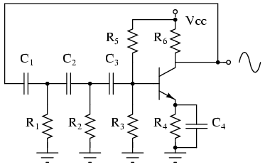
The phase shift oscillator produces a sine wave output in the audio frequency range. Resistive feedback from the collector results in negative feedback due to a 180-degree phase inversion from the base to the collector. The three 60-degree RC...