
Dark Activated Switch circuit

The circuit described is a light-activated relay switch utilizing an ORP12 photocell as the light sensor. The primary function of this circuit is to monitor ambient light levels and activate a relay when the light intensity drops below a predetermined threshold. This capability is useful for applications such as automatic lighting control or alarm systems.
The core component, the ORP12 photocell, exhibits a significant change in resistance based on the intensity of light it detects. Under bright conditions, the resistance can drop to approximately 80 ohms, allowing current to flow freely through the circuit. Conversely, in low-light conditions, specifically at around 50 lux, the resistance increases to over 1 megohm, effectively limiting the current flow. This characteristic enables the circuit to differentiate between varying light levels.
The adjustment of the light sensitivity is facilitated by a variable resistor (VR1), which allows for fine-tuning of the light threshold at which the relay is activated. The resistance value of VR1 can be selected to achieve the desired sensitivity, ensuring that the relay will respond appropriately to the ambient light conditions.
Upon reaching the set light level, the circuit activates a relay, which can then control external devices such as lights or buzzers. The relay contacts are rated to handle the load of the connected devices, providing isolation between the low-power sensing circuit and the higher power loads.
In summary, this circuit effectively combines a light sensor and a relay to create an automated response to changes in ambient light, enhancing functionality in various applications where light control is necessary. Proper selection of components and careful calibration of the sensitivity will ensure reliable operation in the intended environment.This circuit will activate a relay when light falls to a preset level. Light level can be adjusted with VR1 and the relay contacts may be used to operate an external light or buzzer. The light sensor used is the ORP12 photocell. In bright light the resistance of the ORP12 can be as low as 80 ohm and at 50lux (darkness) the resistance increases to over 1 Mohm. The 1M control should provide a wide range for light intensities, if not its 🔗 External reference
Related Circuits
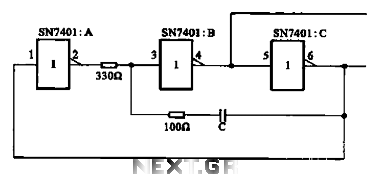
The clock signal generating circuit utilizes an RC configuration, commonly applicable in most TTL systems. This circuit requires a set of six inverters, specifically three inverters from the SN7401 series. The clock frequency is determined by the values of...
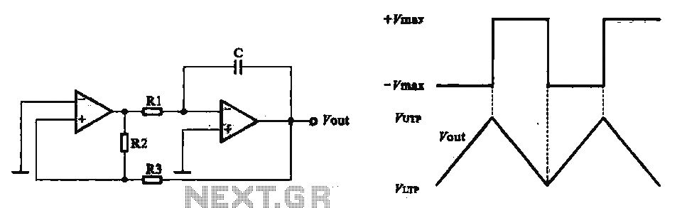
This circuit utilizes two operational amplifiers configured as triangular wave oscillators. It demonstrates a practical application of a relaxation oscillator that employs a voltage comparator to execute the switching function. The schematic in FIG. 2 illustrates the composition of...
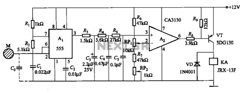
The circuit utilizes a 555 IC in conjunction with capacitors C1, C2, and a metal plate (tablet) M to create a distributed capacitance Co and resistor R1 connected to ground. Resistor R2 forms a self-excited multivibrator, while resistors R3...

A simple technique for measuring frequencies across a wide range with acceptable accuracy limits using a PC is presented. This method follows the basic principle of measuring low frequencies, where the period of a complete wave is measured and...
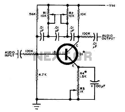
This circuit is designed for selective tuning adjustments between two closely spaced audio tones. The frequency of the circuit is determined by the selected capacitors and resistors in the feedback loop between the collector and base of transistor Q1....
The circuit consists of inverter and charger sections. The inverter section utilizes the NE555 timer, while the charger section is based on the LM317 adjustable regulator. In the inverter section, the NE555 is configured as an astable multivibrator, generating...