
Fully Automatic Emergency Light circuit

The inverter section of this circuit is designed to convert a DC input voltage into an AC output voltage. The NE555 timer, functioning as an astable multivibrator, continuously oscillates to produce a square wave signal at a frequency of 15 kHz. This square wave is crucial for driving the subsequent power amplification stage. The output from pin 3 of the NE555 is a square wave that toggles between high and low states, which is then amplified by the Darlington pair consisting of transistors SL100 and 2N3055. The Darlington configuration allows for high current gain, making it suitable for applications requiring substantial output power. The resistor R4 serves to limit the base current to the transistors, ensuring stable operation and preventing damage due to excessive current.
The charger section of the circuit is responsible for regulating the voltage supplied to a connected battery or load. The LM317 adjustable voltage regulator is employed for this purpose, allowing for precise control over the output voltage. The LM317 can provide a variable output voltage, typically ranging from 1.25V to 37V, depending on the external resistors used in the configuration. This flexibility makes the circuit suitable for various charging applications, accommodating different battery types and voltages.
Overall, this circuit effectively combines the inverter and charger functionalities, making it a versatile solution for powering AC loads while simultaneously providing a regulated DC charging capability. The design emphasizes efficiency and reliability, suitable for use in various electronic applications.The circuit can be divided into inverter and charger sections. The inverter section is built around timer NE555, while the charger section is built around 3-terminal adjustable regulator LM317. In the inverter section, NE555 is wired as an astable multivibrator that produces a 15kHz squarewave.
Output pin 3 of IC 555 is connected to the Darlington pair formed by transistors SL100 (T1) and 2N3055 (T2) via resistor R4.. 🔗 External reference
Related Circuits
The following diagram is for the main circuit of the motor driver. A testing version is shown near the end of this page. It is laid out differently and shows the SN7474 in logic block form and LEDs are...
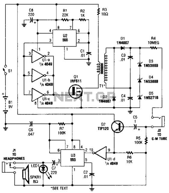
The circuit is constructed using a 4049 hex inverter (U1), two 555 oscillator/timers (U2 and U3), two transistors, a Geiger-Muller tube, and several additional support components. The first 555 timer (U2) is set up for astable operation. The output...
To capture high-speed photographs, a fast shutter or light source is essential. This project involved examining a commercial flash unit to analyze its light profile. A phototransistor was connected in an emitter follower configuration with a low impedance emitter...
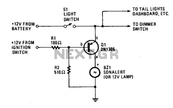
The circuit provides a visible or audible warning when the headlights are on. It utilizes a 2N1305 transistor as a switch to activate either a Sonalert tone generator or a small 12-V lamp. The operating current for the transistor...
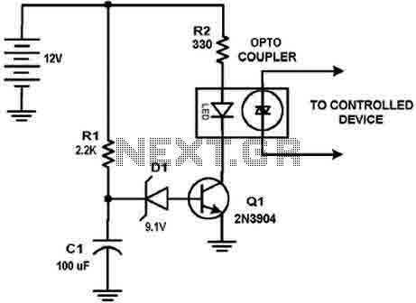
This circuit design was used to switch on device via a LED photocell arrangement (optocoupler) using components R1, C1, D1 and Q1. It produces a delay on powering up to ensure correct sequencing of certain equipment. A very simple...
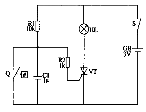
The automatic anti-frost crop controller circuit comprises an electric contact mercury thermometer (Q), a control circuit, ignition devices, and other components. The electric contact mercury thermometer features two platinum electrodes; one acts as a contact electrode inserted at the...