
darklight sensor using transistor

This circuit operates based on the principle of light-dependent resistors (LDRs), which change their resistance according to the ambient light level. In bright conditions, the resistance of the LDR decreases, allowing current to flow through the circuit. When the light level drops below a certain threshold, the resistance increases, triggering the activation of LED D1.
The circuit comprises an LDR connected in a voltage divider configuration with a fixed resistor. The output from this configuration is fed into a comparator circuit, which compares the voltage across the LDR with a reference voltage set by a potentiometer. When the voltage across the LDR exceeds the reference voltage, the comparator output changes state, activating the LED.
To enhance functionality, the circuit includes a variable resistor (VR1-10K), which allows for fine-tuning of the sensitivity. By adjusting this resistor, users can set the desired light level at which the LED will turn on or off. This feature makes the circuit versatile for various applications, such as automatic street lighting or garden lights that activate at dusk and deactivate at dawn.
In summary, this automatic dark detector and light detector circuit is a practical implementation of light sensing technology, providing an efficient solution for automatic lighting control based on ambient light conditions.Automatic dark detector senses darkness. As the light level decreases and LDR meets the maximum threshold resistance, the circuit automatically switches on the LED D1. A light detector senses light. As the light level increases and LDR meets the lowest threshold resistance, the circuit automatically turns on the LED D1.
We can adjust the sensitivi ty using the preset VR1-10K. 🔗 External reference
Related Circuits
This circuit is designed to switch on or off any home or industrial appliance using a TV or DVD remote controller. The circuit can be operated up to a distance. The circuit utilizes an infrared (IR) receiver module, which detects...
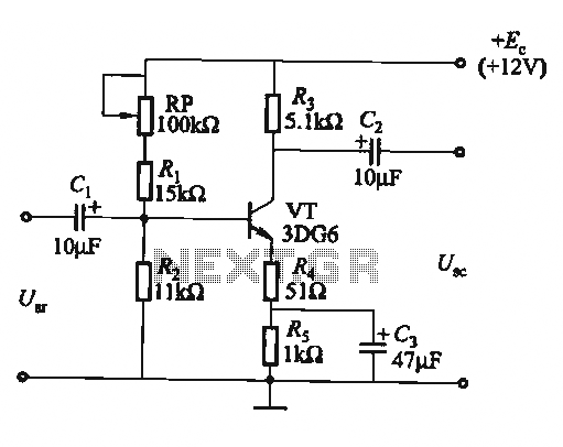
The circuit is a bias circuit for automatic stabilizers that maintains a stable quiescent operating point with good thermal stability. It utilizes a three-pole tube with an NPN type transistor, characterized by a small Iceo. An adjustment potentiometer, RP,...
To avoid excess ripple output on a power supply feeding a heavy load, usually a large value capacitor is chosen following the rectifier. In this circuit, C1 is only a 470uF capacitor. The gyrator principle uses the effect that...
This project implements a network-connected water level sensor that measures the water level in the sump pit of a house. It is connected to the home network and reports the water level by broadcasting UDP packets, allowing any computer...
Quasi square wave resonant converters, also referred to as quasi resonant (QR) converters, facilitate the design of flyback Switch Mode Power Supplies (SMPS) with diminished Electro Magnetic Interference (EMI) and enhanced efficiency. Due to their low noise generation, QR...
Dark Activated Switch or Porch Light Switch. This circuit activates a relay when the light level drops below a preset threshold. The light sensitivity can be adjusted using variable resistor VR1, and the relay contacts can control an external...