
Improved multivibrator circuit

The described circuit appears to be a basic oscillator configuration, likely designed for generating high-frequency signals. The resistors R1 and R2, with their specified resistance values, form part of the timing components that determine the oscillation frequency. The capacitors C1 and C2 play a crucial role in setting the oscillation characteristics, where their capacitance values influence the charge and discharge cycles, ultimately affecting the frequency of oscillation.
In the context of oscillators, the range of 2 to 5 MHz indicates that this circuit is suitable for applications requiring high-speed signal generation. The adjustment of RP through a potentiometer allows for fine-tuning of the resistance, which can be critical for achieving the desired oscillation frequency. This feature enhances the versatility of the circuit, making it adaptable to various operational requirements.
The inclusion of diodes and transistors serves to stabilize the oscillator’s performance by preventing simultaneous saturation. This is important in maintaining the integrity of the oscillation and avoiding distortion in the output signal. Diodes can be used for clamping and protecting the circuit from voltage spikes, while transistors can serve as amplifiers or switches within the oscillator circuit, ensuring reliable operation.
Overall, this circuit design is indicative of a fundamental oscillator application, with components carefully selected to achieve specific operational parameters. The combination of resistors, capacitors, and active components like diodes and transistors allows for a robust design capable of generating stable high-frequency oscillations.Circuit shown (A): R], R2 is 15 ~ 18kn, Cl, C2 is 0.01 ~ 10 "F. Figure (b): oscillation frequency, up to 2 ~ 5MHz, RP is adjusted by potentiometer FIG. (C) access. diodes, transistors can be prevented by two simultaneous saturation stop vibration.
Related Circuits
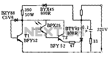
The circuit is designed to activate when the light intensity exceeds 700lx. In this configuration, a phototransistor and the BFY52 transistor are used to trigger the BTY91 thyristor with a current. When light strikes the phototransistor, a positive trigger...
The thermocouple cold junction compensation circuit and the MAX6675 converter circuit diagram form a temperature measuring system. The system utilizes a K-type thermocouple connected to the T terminals of the MAX6675, with the cold junction grounded. An 8051 microcontroller...
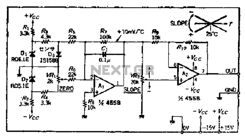
A temperature sensor can be created using a standard silicon diode, which produces approximately 2.2 mV per degree Celsius variation. An operational amplifier (OP amplifier) is utilized with a positive reference temperature (room temperature). The output signal is amplified...
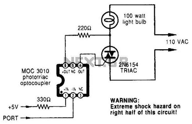
A microcomputer-to-triac interface utilizes a phototriac optoisolator to safely isolate logic signals, allowing direct control of high-power loads. This circuit can function as either an on/off switch or a proportional phase control, depending on the input waveforms and the...
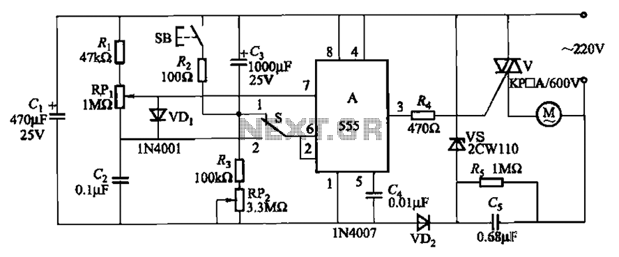
The circuit illustrated in Figure 3-12 incorporates variable speed and timing control functions. When switch S is set to position 1 and button SB is pressed, the motor initiates operation. After a predetermined delay, the motor automatically shuts down....

The LA4440 is a dual-channel audio power amplifier integrated circuit (IC) designed for stereo and bridge amplifier applications. In dual mode, it provides significant audio amplification for various audio systems. The LA4440 audio power amplifier is engineered to deliver high-quality...