
Electric thermos temperature detection control circuit

The electric thermos temperature detection control circuit operates by integrating several key components to ensure efficient temperature management. The control circuit for the boiler heater is responsible for regulating the heating element's operation based on the temperature readings from the thermistor or temperature sensor. This regulation ensures that the water or liquid within the thermos maintains the desired temperature without overheating or cooling excessively.
The heater insulation component plays a critical role in minimizing heat loss. It surrounds the heating element and the thermos body, providing thermal resistance that helps maintain the internal temperature. This insulation is crucial for energy efficiency and prolongs the heating duration.
The electrical magnetic pump motor drive circuit facilitates the movement of liquid within the thermos. This circuit typically includes a relay or transistor that controls the operation of the pump motor. When activated, the pump circulates the liquid, ensuring uniform temperature distribution and preventing localized overheating.
Additionally, the heating and warming light circuit is designed to provide visual feedback regarding the operation of the heating system. This circuit may include LED indicators that illuminate when the heating element is active or when the thermos reaches the set temperature. Such indicators enhance user interaction by providing clear status updates.
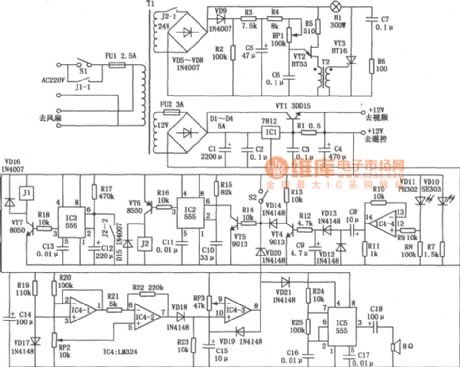
Overall, the electric thermos temperature detection control circuit integrates these components into a cohesive system that efficiently manages temperature control, enhances user experience, and ensures optimal performance of the electric thermos.Electric thermos temperature detection control circuit Electric thermos shows the temperature detection control circuit. It is mainly by the control circuit of the boiler heate r and heater insulation, electrical magnetic pump motor drive circuit, as well as heating and warm light circuit configuration.
Related Circuits

Here is a design for a DC motor speed control featuring: Efficient PWM H-bridge MOSFET architecture. Supply (battery) voltage range from 4.2 to 13 volts. High current capacity for driving large motors (65 amps max). Input compatible with standard...
This active antenna schematic can be used to frequency range from 10 KHz to 100 MHz. The length of the Antenna can be between 0.5 to 1 meter long. The power consumption is 20-30mA. More: Use the shortest possible...
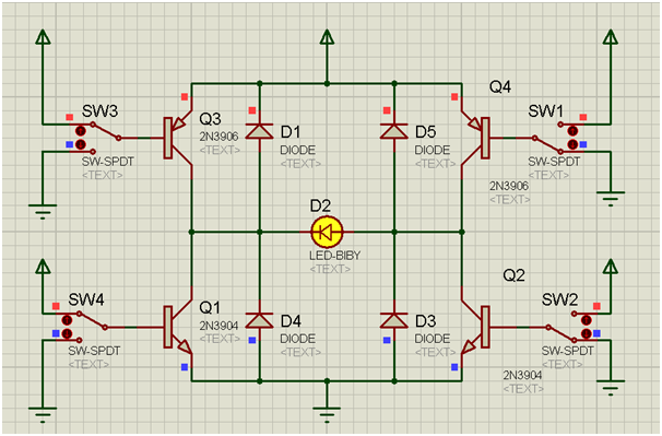
An H-bridge is a circuit configuration that enables the application of voltages in both directions. It permits higher voltage and current to be applied to the load while controlling the direction using a low voltage signal. The accompanying diagram...
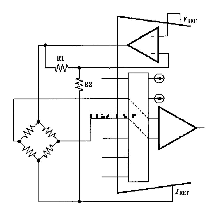
The circuit voltage source VREF excites the sensor bridge. The excitation voltage VEX is defined as VREF (1 + R1/R2), where the bridge is connected at both ends. The sensor bridge circuit is designed to convert a physical quantity, such...
This circuit utilizes a dual operational amplifier (TL082) to create a voltage-controlled oscillator (VCO). The specified component values allow the output frequency to range from 100 Hz to 10 kHz when the input control voltage is between 0.05 and...
Two-Tone Siren Circuit Schematic Using One IC. This circuit is designed for children's entertainment and can be installed on bicycles, battery-powered cars, motorcycles, as well as models and various games and toys. It includes a switch (SW1) for operation. The...