Darlington phototransistor type light control switch circuit diagram sensitive application
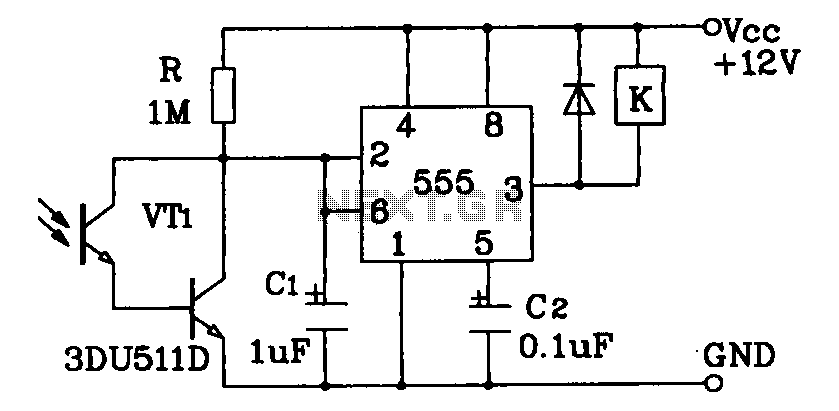
Darlington phototransistor type light-sensitive switch control circuit application. The Darlington type phototransistor serves as a sensitive element, capable of detecting low light levels for the detection of reflected light signals.
The Darlington phototransistor circuit utilizes a pair of transistors configured to amplify the current, making it highly sensitive to light. This configuration is particularly effective in applications where low levels of light need to be detected, such as in reflective light sensors. The circuit operates by allowing light to strike the phototransistor, which generates a small current proportional to the intensity of the incoming light. This current is then amplified by the Darlington pair, resulting in a significant increase in output current.
In a typical application, the circuit may include additional components such as resistors to set the biasing conditions for the phototransistor, and capacitors for noise filtering. The output can be connected to a microcontroller or a relay, enabling the control of larger loads based on the detected light levels. The design ensures that the circuit can function effectively in various lighting conditions, making it suitable for automation systems, security devices, and other light-sensitive applications.
Overall, the Darlington phototransistor circuit represents an efficient solution for detecting reflected light signals, with its high sensitivity and amplification capabilities making it ideal for a wide range of electronic applications.Darlington phototransistor type light-sensitive switch control circuit application As a result of Darlington type phototransistor do sensitive element, the low light sensitive for the detection of the reflected light signals.
