
Data Based Voltage Controlled Amplifier

This project utilizes the VCA_Setup and VCA_Data components to facilitate various types of simulations within the Advanced Design System (ADS). The VCA_Setup component is responsible for establishing the parameters required for the simulations, while VCA_Data processes the results generated from these simulations.
The schematics included in the project serve specific purposes. "Amp_wBothMatches_setup.dsn" acts as the foundational setup for circuit extraction, enabling the retrieval of essential circuit-level data from "Amp_wBothMatches_subnet.dsn." This data is critical for subsequent behavioral simulations.
The "Amp_wBothMatches_circuit_1tone.dsn" schematic implements a one-tone swept control voltage and input power harmonic balance simulation, allowing for detailed analysis of the amplifier's performance under varying input conditions. The results from this schematic provide insights into the frequency response and stability of the circuit when subjected to different control voltages.
For behavioral simulations, "Amp_wBothMatches_behavioral_1tone.dsn" utilizes the previously extracted data to perform a similar one-tone swept analysis, but from a behavioral perspective. This approach allows for a broader understanding of how the amplifier behaves under different operational scenarios, particularly when considering non-ideal conditions.
The envelope simulations are handled by "Amp_wBothMatches_circuit_env.dsn" and "Amp_wBothMatches_behavioral_env.dsn," which focus on the circuit's response to varying envelope signals. These simulations are essential in communications applications where the signal envelope plays a critical role in performance.
The results from these various simulations are stored in designated datasets, providing a structured approach to data management within the project. The comparison illustrated in Figure 1 emphasizes the importance of appropriate sampling rates, as the findings indicate that a sampling strategy of 2 V and 4 V fails to adequately represent the circuit's behavior at intermediate control voltages, such as 3 V. This highlights the need for finer sampling in order to capture the nuances of the circuit's response accurately, thereby ensuring reliable and effective design outcomes.The VCA project illustrates the use of the VCA_Setup and VCA_Data components in ADS. These components are part of the ADS behavioral model suite found under the System - Data Models palette. "Amp_wBothMatches_setup. dsn" is a schematic for extraction of circuit level information for "Amp_wBothMatches_subnet. dsn. " The result is in the dataset "Amp_wBothMatches_setup. ds" which will be used by VCA_Data for behavioral level simulations. "Amp_wBothMatches_circuit_1tone. dsn" is a schematic for a circuit level 1-tone swept control voltage and swept input power harmonic balance simulation of "Amp_wBothMatches_subnet. dsn. " The result is in the dataset "Amp_wBothMatches_circuit_1tone. ds. " "Amp_wBothMatches_behavioral_1tone. dsn" is a schematic for a behavioral level 1-tone swept control voltage and swept input power harmonic balance simulation of "Amp_wBothMatches_subnet.
dsn" using VCA_Data along with the dataset "Amp_wBothMatches_setup. ds. " The result is in the dataset "Amp_wBothMatches_behavioral_1tone. ds. " "Amp_wBothMatches_circuit_env. dsn" is a schematic for a circuit level circuit envelope simulation of "Amp_wBothMatches_subnet. dsn. " The result is in the dataset "Amp_wBothMatches_circuit_env. ds. " "Amp_wBothMatches_behavioral_env. dsn" is a schematic for a behavioral level circuit envelope simulation of "Amp_wBothMatches_subnet. dsn" using VCA_Data along with the dataset "Amp_wBothMatches_setup. ds. " The result is in the dataset "Amp_wBothMatches_behavioral_env. ds. " In Figure 1, a comparison of circuit and behavioral level results is given for Harmonic Balance simulation. The sampling for VCA_Setup is 2 V, 4 V and 6 V, a 2 V spacing. The deviation for Vcontrol = 3 V illustrates the effect of improper sampling for VCA_Setup. Sampling at 2 V and 4 V is simply too coarse to properly capture the response at 3 V. 🔗 External reference
Related Circuits
Since the volume control is after the gain stage, the preamp can be easily overloaded. I tried to limit the input signal by mounting a 470 k resistor in series with the CD input. A voltage divider is formed...
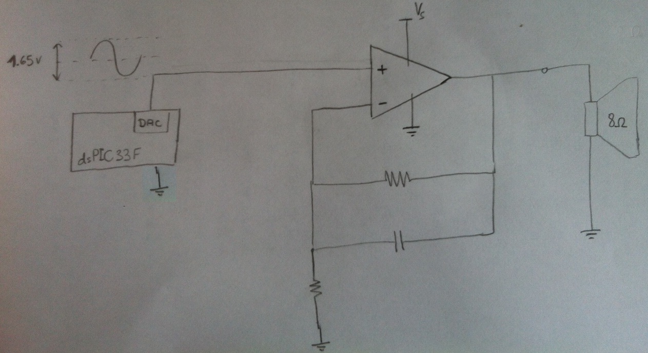
Design a circuit in which a microcontroller produces a signal and then uses an amplifier to drive an 8-ohm speaker. The LM386 has been used previously, but it cannot exceed 1W, which is insufficient. Additionally, a second-order anti-aliasing low-pass...
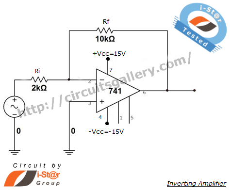
An inverting amplifier is one of the most widely used operational amplifier circuits. The output adjusts in a manner that counteracts changes caused by the input, thereby preventing saturation and ensuring stability. By connecting a resistor from the output...
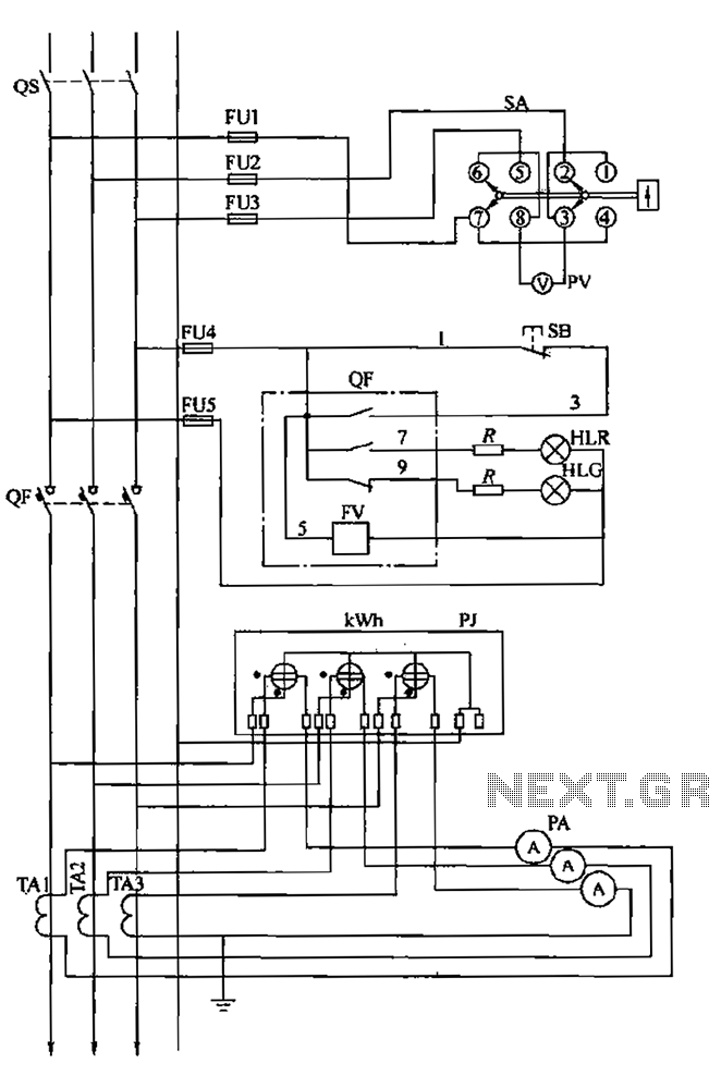
The BSL is illustrated in a low-voltage distribution panel wiring diagram. It consists of three main components: the voltage measuring circuit, secondary circuit protection, and the energy metering circuit. (1) The voltage measuring circuit includes a voltage switch (SA)...
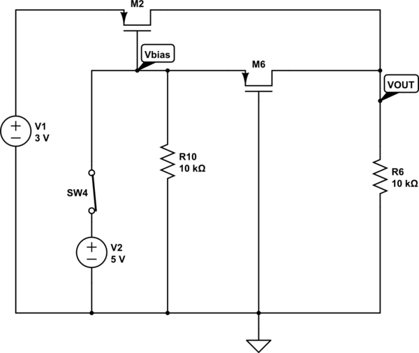
The output voltage (VOUT) is intended to be 3V when the switch is open and 5V when the switch is closed. The simulation correctly reflects the desired outcome when the switch is open; however, it does not perform as...
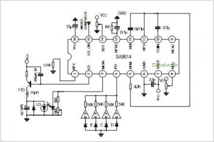
The SA9618A is designed for ALPC and signal conversion between a CD optical pickup and a decoding chip. This integrated circuit (IC) features an interconnection for a general CD optical pickup photodiode bias voltage VREF generation circuit, an RF...