
Op Amp 741 Inverting Amplifier Circuit Simulation with output wave form and working

The inverting amplifier circuit utilizes an operational amplifier (op-amp) configured with feedback to achieve a desired gain while maintaining high stability. The circuit typically consists of an op-amp, two resistors (Rf and Ri), and the input signal. The inverting input of the op-amp is connected to the input signal through the resistor Ri, while the feedback resistor Rf connects the output to the inverting input. The non-inverting input is grounded, establishing a reference point.
When a voltage signal is applied to the input, the op-amp amplifies the difference between the inverting and non-inverting inputs. The feedback resistor Rf plays a crucial role in determining the gain of the amplifier, which is given by the formula: Gain = -Rf/Ri. The negative sign indicates that the output is inverted relative to the input.
The operational amplifier's high open-loop gain ensures that even a small difference between the inverting and non-inverting inputs results in a significant output change. To maintain linear operation and prevent saturation, the feedback mechanism continuously adjusts the output to keep the inverting input at virtual ground. This results in a stable output that accurately represents the amplified input signal, albeit with an inverted polarity.
The frequency response of the inverting amplifier is influenced by the bandwidth of the op-amp and the values of Rf and Ri. At lower frequencies, the gain remains constant as dictated by the resistor values. However, as frequency increases, factors such as the op-amp's slew rate and bandwidth limitations can affect performance, potentially leading to distortion or reduced gain at higher frequencies.
In summary, the inverting amplifier is a fundamental building block in analog electronics, widely used for its ease of implementation and stability in signal processing applications. Its ability to provide precise gain control while maintaining a consistent output makes it essential for various applications, including audio processing, signal conditioning, and sensor interfacing.Inverting amplifier is one of the most popular Operational Amplifier circuits. The output changes in such a way that tries to avoid saturation and counteract the change caused by the input. This makes the amplifier stable. The amplifier tries to resist change and so avoid saturation. we can therefore afford to lose some of this gain by connecting a suitable resistor across the amplifier from the output terminal back to the inverting input terminal to both reduce and control the overall gain of the amplifier. This produces a very stable Operational Amplifier based system. The polarity of input voltage gets inverted at the output. If a sine wave is fed to the input of this amplifier, the output will be amplified sine wave with 180 ° phase shift.
It has so many applications for example Audio amplifier, Pre amplifier, etc. The feedback will try to ensure that the inverting input is very close to 0v. This is because the difference between the inputs must be only µV if the output is not saturated. The inverting input is called a virtual ground. If Vin rises then the inverting input is greater than non-inverting and so Vout goes rapidly negative until the two inputs are once again equal (orat leastonly µV`s different) For the amplifier to work properly the output must be able to change very quickly in order to react to the changes in the input. This limits the maximum frequency at which the amplifier can operate. The ratio of Vin and Vout depends on the ratio of the resistors in the potential divider and so, at low frequencies, the gain depends only on the values of Rf and Ri.
🔗 External reference
Related Circuits
This radio modem is widely used for amateur radio packet applications. It is powered by the data and control lines, eliminating the need for additional power sources. The radio modem operates by facilitating packet data communication over amateur radio frequencies....
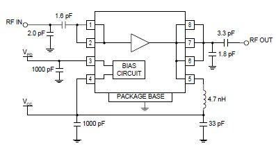
The RF2126 high-power linear amplifier IC, manufactured by RFMD, can be utilized to design a simple yet highly efficient amplifier for 2.45 GHz ISM applications, including WLAN and POS terminals. This component also serves as the final stage in...
The transmitter provides an optical link (infrared) for headphones. Three infrared LEDs (IR) are powered by T1, with P1 used to adjust the current level. The current consumption of this headphones infrared transmitter is approximately 60mA at 9V. The infrared...
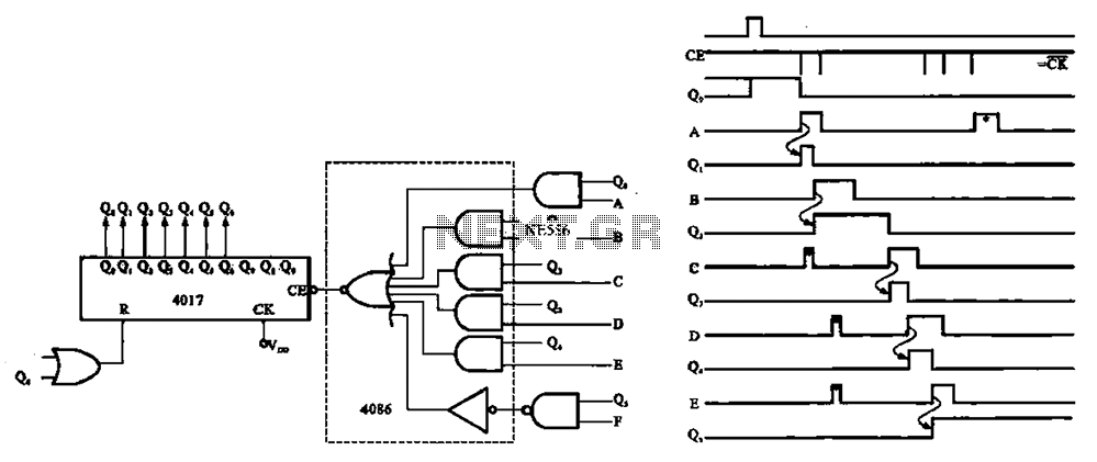
An asynchronous counter is illustrated in this circuit. It operates without a clock synchronization signal, making it suitable for use in a random counter or as an independent unit circuit. An asynchronous counter, also known as a ripple counter, is...

The inquiry pertains to whether a specific circuit will invert the input signal. The operational amplifier (op-amp) is single-supplied with a voltage of 5V, and the input signal varies between 0V and 5V. The question arises regarding the output...
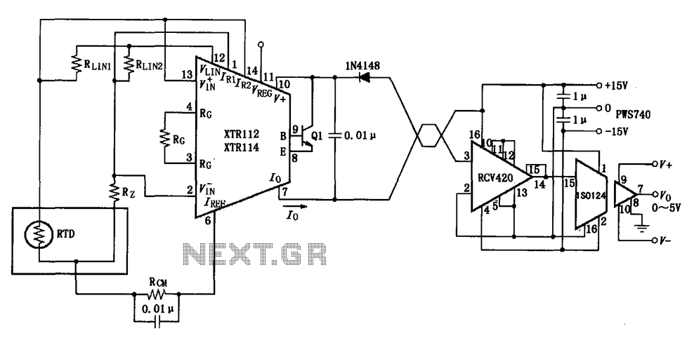
The RTD temperature data collected at the scene is converted into a voltage using the XTR112/114. This voltage is further transformed into a 4 to 20 mA current output, which is then transmitted via a twisted pair. The RCV420...