
Data separator

The data separator circuit is crucial for accurately processing information from 8-inch floppy diskettes formatted in the IBM 3870 standard. Its primary function is to separate and synchronize data and clock signals, ensuring that data is read correctly from the diskette. The circuit employs a one-shot multivibrator (Nl) to shape the unseparated data signal (A), providing a clean output that is essential for reliable data transmission.
The adjustment of trimmer (PI) to achieve a pulse width of 1 µs for signal (B) is a critical step. This calibration ensures that the PLL (N2) can maintain synchronization with the incoming data stream, operating at a stable frequency of 500 kHz. The PLL's output being 90 degrees out of phase is an intentional design choice that allows for effective phase comparison and adjustment, further enhancing the reliability of the data separation process.
The D-type flip-flop (N3) serves as a frequency divider, effectively halving the frequency of the input signal (C) and generating a corresponding output that is used in the subsequent stages of the circuit. Meanwhile, flip-flop (N4) operates as a shift register, continuously monitoring the incoming pulse stream for any interruptions. The detection of four consecutive missing pulses indicates a potential loss of synchronization, prompting the circuit to reestablish alignment using signal (E). This self-correcting mechanism is vital for maintaining data integrity, ensuring that the negative edge of clock pulse (D) remains accurately positioned within the data cell, thus facilitating proper data recovery from the floppy diskette.
Overall, the design of the data separator circuit illustrates a sophisticated approach to handling legacy data storage formats, emphasizing the importance of timing and synchronization in digital signal processing.The data separator is intended for use with 8" flexible diskettes with IBM 3870 soft sectored format. The circuit delivers data and clock (B) and clock pulses (D). These two signals must be in such a sequence that the negative edge of the clock pulse is at the middle of a data cell.
Unseparated data (A) from the floppy unit is shaped with one shot Nl. Trimmer PI should be adjusted so that pulses (B) are 1 ?& wide. This signal synchronizes PLL N2 with a free running frequency adjusted to 500 kHz. The output of the PLL is 90° out of phase with its input. D-type flip-flop N3 is connected as a divider by two and changes state at each positive edge of (C). N4, connected as a shift register, looks for four consecutive missing pulses. When this happens, the circuit is resynchronized with (E) so that the negative edge of (D) is in the middle of a data cell.
Related Circuits
The MSF transmitter transmits time data bit-by-bit over 60 seconds each minute by modulating a 60 kHz carrier frequency. It employs a continuous wave (CW) signal. Two bits are sent every second through variations in the duration and number...
The VCA project demonstrates the use of the VCA_Setup and VCA_Data components in ADS. These components belong to the ADS behavioral model suite located under the System - Data Models palette. The schematic "Amp_wBothMatches_setup.dsn" is designed to extract circuit-level...
The Data Recorder (A3007) is a LWDAQ device that decodes and records subcutaneous transmitter (SCT) messages. The A3007 processes the signal generated by a demodulator, such as the Demodulating Amplifier (A3017), to identify valid SCT message sequences. It stores...
Version V2.9 supports a GPS receiver with an ANTARIS chipset while simultaneously utilizing the internal temperature sensor of the MS5534A and the external DS1820 sensor. This version is compatible with 24C256, 24C512, or 24C1024 EEPROMs and includes an internal...
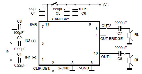
The car radio application utilizes a Class AB Audio Power Amplifier, typically featuring the TDA7360 IC. This amplifier provides 22W output in either bridge or stereo configuration and includes several beneficial features such as a minimal requirement for external...

The CA3140 is a 4.5 MHz BiMOS operational amplifier featuring MOSFET inputs and a bipolar output. This operational amplifier integrates the benefits of PMOS transistors and high voltage performance. The CA3140 operational amplifier is designed to provide high-speed performance while...