
Data Slicing Techniques for UHF ASK Receivers

The data slicers in the Maxim UHF receiver and transceiver series are critical components designed to process incoming data signals efficiently. These devices utilize advanced signal processing techniques to extract digital information from analog waveforms, ensuring that data integrity is maintained in various communication environments.
The MAX1470, MAX1473, and MAX1471 receivers are engineered to operate within specific frequency ranges, providing robust performance in UHF applications. The data slicers within these receivers employ threshold detection methods to discern between high and low signal levels, effectively converting the analog signal into a clean digital output. This function is essential for minimizing errors in data transmission, especially in environments with significant noise or signal degradation.
Similarly, the MAX7030 and MAX7032 transceivers integrate data slicers that facilitate bidirectional communication. These transceivers are designed for applications requiring both transmission and reception of data, making the data slicer functionality vital for maintaining the clarity and reliability of the communication link. The design of these data slicers incorporates features such as adjustable thresholds and filtering capabilities, allowing for customization based on specific application needs.
Overall, the operation of data slicers in the Maxim UHF series is pivotal for achieving high-performance communication systems, ensuring that digital data is accurately captured and transmitted, thereby enhancing the overall efficacy of wireless communication technologies.This application note explains the operation of the data slicers found in the Maxim line of UHF receivers like the MAX1470, MAX1473, and MAX1471 and transceivers like the MAX7030 and MAX7032.. 🔗 External reference
Related Circuits
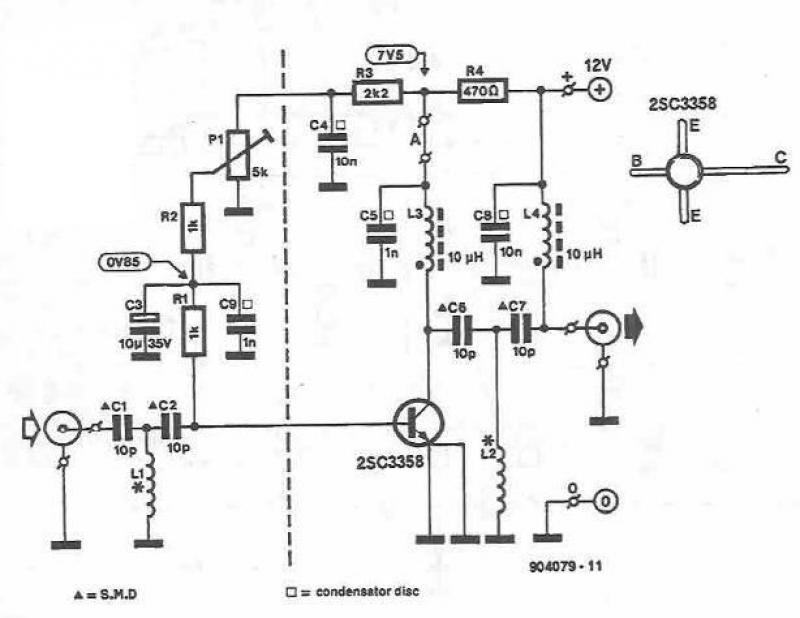
This UHF amplifier circuit project is beneficial for enhancing weak TV signals. The amplifier provides a gain of 10-15 dB within a frequency range of 400 to 850 MHz. To ensure optimal performance and reliability, the PCB tracks should...
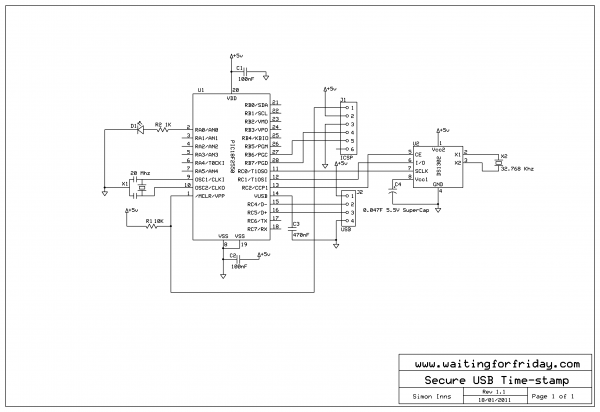
This project implements a USB device that provides a real-time clock for time-stamping events in a non-networked embedded computer environment. For embedded applications requiring periodic time-stamping (such as entry-system logs and configuration audit logs), an accurate real-time clock is...
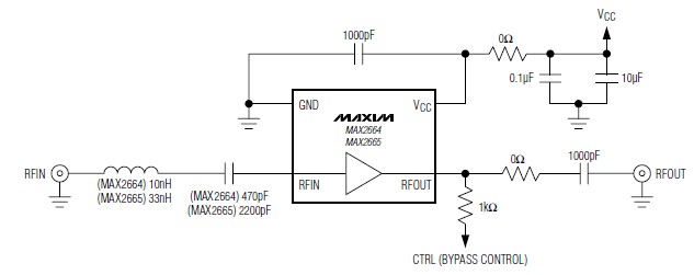
A simple, low-cost, and ultra-compact VHF/UHF low-noise amplifier circuit can be designed using the MAX2664 and MAX2665 ultra-compact LNAs for VHF/UHF applications. These devices incorporate a broadband LNA with an integrated bypass switch. The MAX2664 covers the UHF frequency...
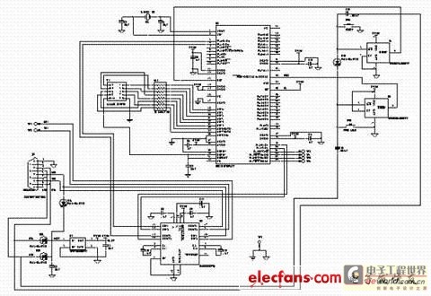
This text discusses the MSC1210 microcontroller as the core of a high-accuracy temperature measurement system, which includes signal processing and communication capabilities. The system is designed for easy expansion, allowing for accurate measurements and fast data acquisition. The hardware...
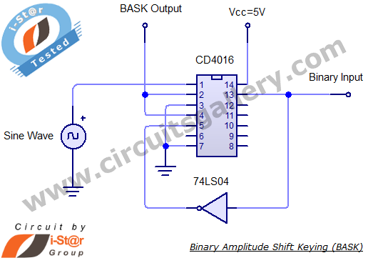
Binary Amplitude Shift Keying (BASK), also known as On-Off Keying (OOK), is a digital modulation technique where the amplitude of the carrier signal is altered according to binary data. This modulation scheme is utilized for transmitting digital information over...
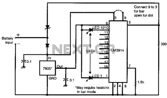
Many amateur receivers are equipped with an S meter that does not operate logarithmically. The proposed circuit is intended to enhance such receivers. Although integrated circuits like the CA3089 or CA3189 are not commonly used today, they play a...