
UHF amplifier circuit

The UHF amplifier circuit is designed to improve the reception of television signals, particularly in areas where the signal strength is insufficient for clear viewing. The circuit operates efficiently within the UHF band, specifically from 400 to 850 MHz, making it suitable for a wide variety of television broadcasts. The gain of 10-15 dB indicates that the amplifier can significantly enhance weak signals, making it easier for the television to process and display the incoming data.
The printed circuit board (PCB) design is critical for the performance of the amplifier. The recommendation to cover the PCB tracks with tin serves to improve solderability and reduce oxidation, which can degrade circuit performance over time. The use of surface-mount device (SMD) components allows for a compact design and minimizes the length of signal paths, which is essential for maintaining signal integrity at high frequencies.
The power supply circuit is straightforward, utilizing a 78L12 voltage regulator to provide a stable 12 V output. This regulator is efficient for low-current applications and helps ensure that the amplifier operates within its specified voltage range, thereby maximizing reliability. The coupling capacitor, which connects the TV to the amplifier, is crucial for blocking any DC voltage while allowing the AC signal to pass through. The specified values of 10-47 pF for this capacitor are appropriate for maintaining the frequency response of the circuit.
Calibration of the amplifier is an important step to ensure optimal performance. The adjustment of the potentiometer P1 allows for fine-tuning of the gain to match the specific signal conditions. By starting with the cursor in the middle of its range, the user can make adjustments based on the received signal quality, aiming for a collector current of 5-15 mA, which indicates that the transistor is operating effectively within its linear region. This careful calibration process is essential for achieving the best possible image quality on the television.This UHF amplifier circuit electronic project can be useful in situations where the TV signal is weak. The UHF amplifier circuit has a gain of 10-15 dB in a frequency range between 400 and 850 MHz. To obtain optimum performance and good reliability, the PCB tracks should be covered with tin. At each disc capacitors C4, C5, C8 and C9, by one of the girls is glued directly on board. All other terminals are to be cut as short as possible and will use SMD components. Power is from a simple source of 12 V built 78L12 stabilizer would be appropriate. TV will be connected to the amplifier through a small coupling capacitor (10-47pF). To calibrate the assembly bring P1 cursor in the middle of his race and then adjust it to obtain the best image quality (in practice, and you get the collector current of transistor of 5-15 mA). 🔗 External reference
Related Circuits
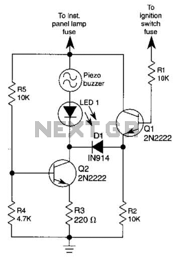
The base of Q1 is connected to the car's ignition circuit; the easiest point to make that connection is at the ignition switch fuse in the car's fuse panel. Also, one side of the piezoelectric buzzer is connected to...
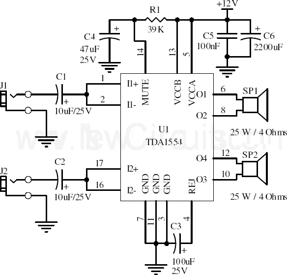
This document presents a 22-watt stereo audio power amplifier circuit diagram utilizing the TDA1554 integrated circuit from NXP Semiconductors (formerly known as PHILIPS Semiconductors). The circuit is designed to amplify stereo signals effectively. It dissipates approximately 28 watts of...
Fans can be controlled remotely with a switch that allows for speed adjustments, and this remote control can also be integrated with other household switches. Its primary feature is the use of a sub-transmission ultrasonic transmitter, which operates without...
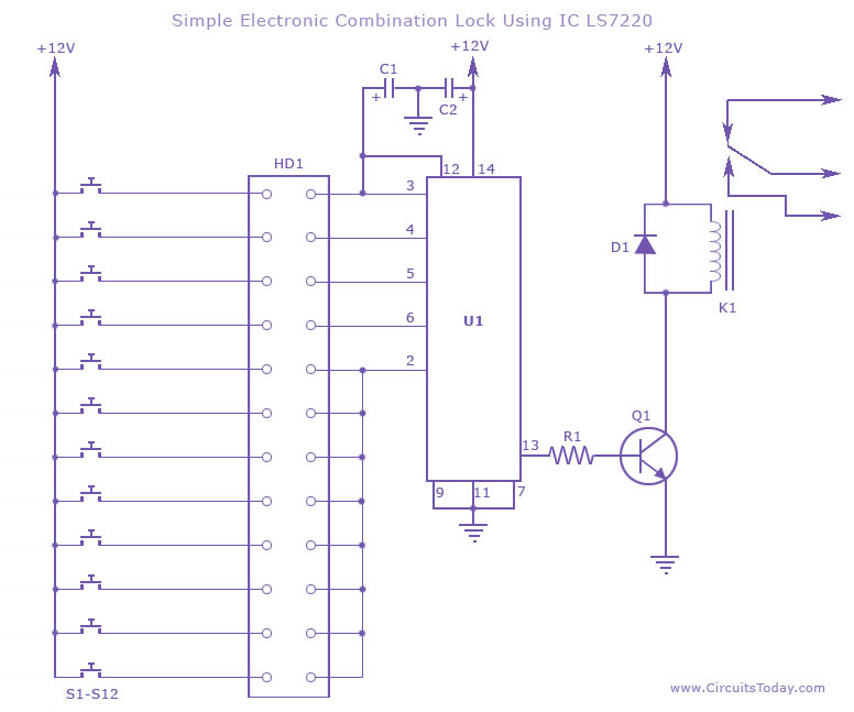
This circuit diagram illustrates a simple electronic combination lock utilizing the IC LS7220. It is designed to activate a relay for controlling any device (on & off) when a specific combination of four digits is entered. The circuit operates...
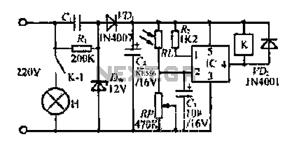
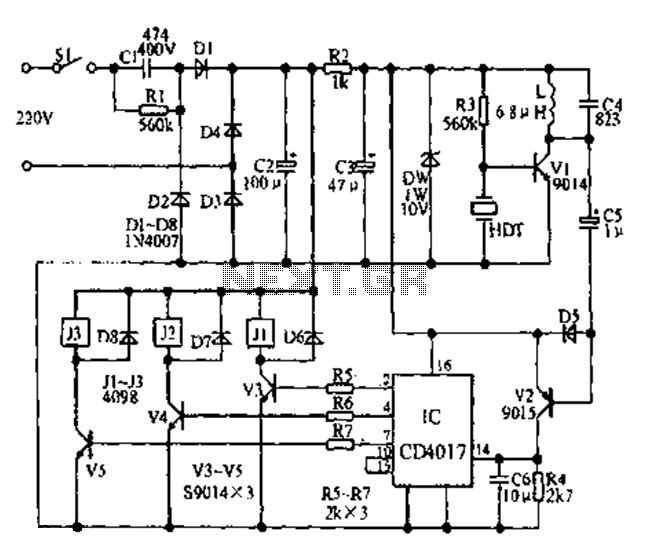
At dawn, light illuminates the photosensitive resistor RL, causing its resistance to decrease. This switch IC (2) exhibits a high electrical footprint. When light is present, the relay K does not activate. At night, in the absence of light,...
After conducting experiments with a rotary encoder connected directly to keyboard switches, it was found that the keyboard controller IC (an Intel P8049AH in this case) is unable to detect pulses that are too narrow. Testing involved rotating the...