
DC/AC inverter

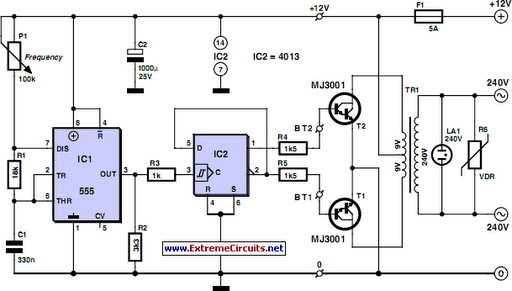
The circuit operates as a basic inverter, converting DC voltage into AC voltage using a multivibrator oscillator and a transformer. The multivibrator, formed with the 7400 or 7404 IC, generates a square wave signal at a frequency of approximately 60 Hz, which is typical for household AC power in many regions. This square wave signal is fed into the bases of the transistors TR1 and TR3, which act as driver transistors. These transistors amplify the current from the IC to a level sufficient to drive the larger power transistors TR2 and TR4, which are responsible for switching the load.
The load is connected to the transformer, which is the critical component for voltage conversion. In this configuration, the transformer is designed to step up the voltage from 12V to 220V AC. The primary winding of the transformer is connected to the switching transistors, while the secondary winding provides the output voltage. It is essential to ensure that the transformer is rated for the appropriate power levels, specifically to handle the maximum current of 3 A flowing through the circuit.
The use of bold wiring in certain sections of the circuit diagram indicates that these paths must accommodate the higher current levels, requiring thicker gauge wire to prevent overheating and ensure reliability. This design consideration is crucial for maintaining the integrity of the circuit during operation.
Overall, this inverter circuit is a practical solution for converting low-voltage DC power into standard household AC voltage, suitable for powering various electrical devices. Proper attention to component ratings, especially for the transformer and transistors, is vital to ensure safe and efficient operation.It is using the IC-type multi-vibrator for the oscillator of the alternating current. The frequency is about 60 Hz. I used 7400 as the IC for the oscillator but 7404 is OK. The signal of the oscillator has the switching operation with TR1-TR4. TR2 and TR4 are the transistor for the main switching. Because these transistors are difficult to drive directly from the IC, they make amplify in the electric current using TR1 and TR3. Because the comparatively big electric current (about 3 A) flows through the part of the line that the circuit diagram is bold, the thick wiring materials are used. I was asked about 220V output from some readers. The output voltage of the inverter is decided only in the transformer. You can use the transformer with 220V as for primary(input) and 12V as for secondary(output). At my circuit, primary and secondary should be used oppositely. Then, you will be able to get AC220V from DC12V. 🔗 External reference
Related Circuits
Although modern electrical appliances are increasingly self-powered, particularly portable ones used for camping or summer holidays, a source of 230 V AC is sometimes necessary. When the power requirement remains relatively low—30 VA in this case—it is straightforward to...
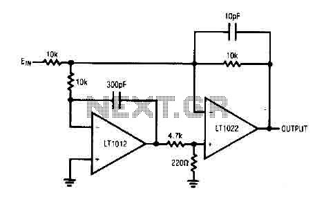
The circuit comprises a low drift LT1012 device and a high-speed amplifier LT1022. It functions as a unity gain inverter, with the summing node located at the junction of three 10k ohm resistors. The circuit monitors the summing node...
An Inverter is a device that converts 12 volts d.c to 120 volts a.c., which is what we use in our homes. This project will handle about 300 watts, which is perfect for lights, small T.V.s and radio equipment....
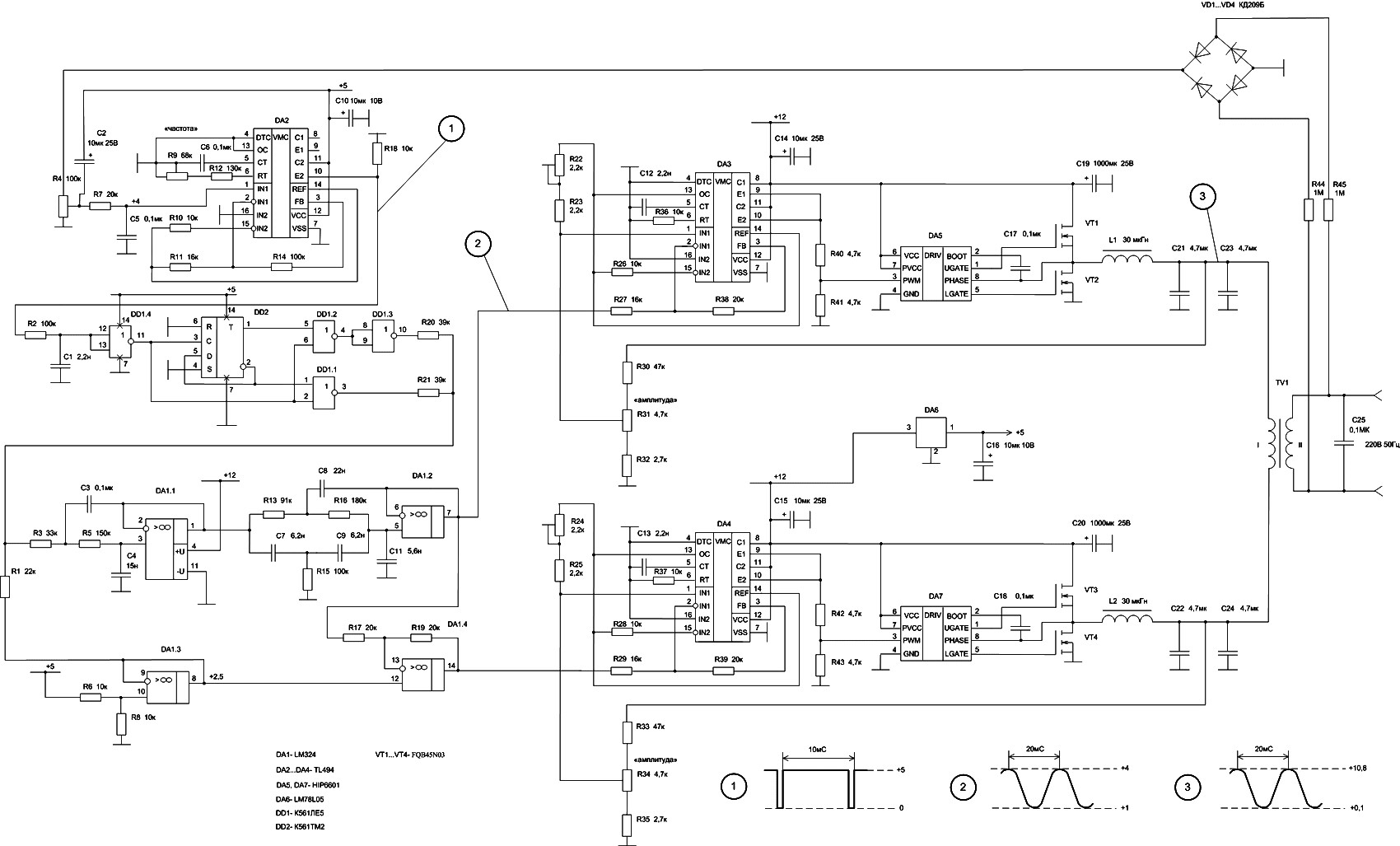
The 50W inverter circuit is built using the power MOSFET FQB45N03 and the IC TL494. This inverter converts a 12-14V DC input from a car battery into a 220V AC output with a 50Hz sine wave frequency. The main...

This article describes a DC-AC inverter circuit that generates the high-voltage AC signal required to drive an electroluminescent (EL) panel. It is based on the Sipex SP4425 EL lamp-driver IC. The DC-AC inverter circuit utilizes the Sipex SP4425 integrated circuit,...
This document outlines a basic circuit designed to power high impedance, high voltage, low current devices such as electroluminescent (EL) backlights and fluorescent tubes. The project originated from the need for a simple yet flexible inverter circuit for an...