
DC-AC inverter targets electroluminescent applications

The DC-AC inverter circuit utilizes the Sipex SP4425 integrated circuit, which is specifically designed to power electroluminescent panels. The SP4425 is capable of converting a low-voltage DC input into a high-voltage AC output, which is essential for the operation of EL panels. The inverter circuit typically consists of several key components, including the SP4425 IC, capacitors, resistors, and inductors, which work together to create the necessary oscillation and voltage amplification.
The SP4425 operates by generating a square wave signal that is fed into a transformer or an inductor. This signal is then transformed into a higher voltage AC signal suitable for driving the EL panel. The circuit configuration may include feedback mechanisms to stabilize the output voltage and ensure consistent performance under varying load conditions.
Capacitors play a crucial role in filtering and smoothing the output AC signal, while resistors may be used to set the operating frequency and ensure proper biasing of the circuit. Inductors are essential for energy storage and transferring energy from the input to the output in a controlled manner.
Overall, this inverter circuit is designed for efficiency and reliability, enabling the effective operation of EL panels in various applications such as backlighting, signage, and decorative lighting. The use of the Sipex SP4425 IC simplifies the design process, allowing for compact and cost-effective solutions in electroluminescent lighting systems.This article describes a dc-ac inverter circuit that generates the high-voltage ac signal required to drive an electroluminescent (EL) panel. It`s based on the Sipex SP4425 EL lamp-driver IC 🔗 External reference
Related Circuits
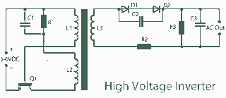
A 3V to 1000V inverter circuit has been constructed, but it is not functioning as intended. The creator seeks expert assistance to identify potential errors in the circuit design. Additionally, there is uncertainty regarding the transformer construction, as the...
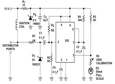
The sections available in this datasheet cover general design considerations for the 555 timer, frequently asked application questions (FAQ), design formulas, and examples of innovative applications. Examples of applications include a Missing Pulse Detector, Pulse Width Modulation (PWM), Tone...
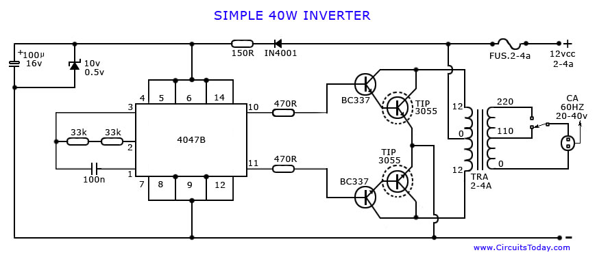
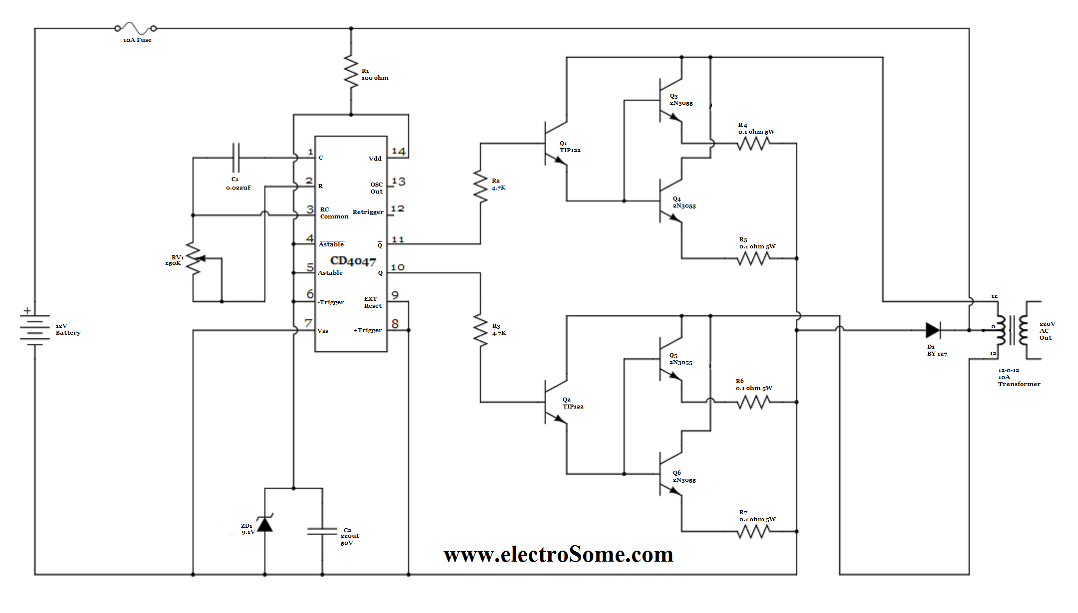
An article on how to create an inverter using a simple 40-watt inverter circuit diagram and schematics. This inverter converts 12 volts to 220 volts using the CD4047 integrated circuit. The described inverter circuit utilizes the CD4047 IC, which is...
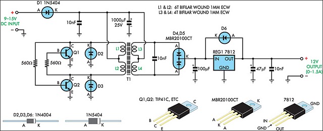
When operating 12V electronic devices from lead-acid battery banks, the voltage supplied to the appliance can fluctuate significantly, ranging from below 11V when the batteries are discharged to over 14V during the charging process. Many appliances are not capable...
For basic requirements, square wave inverters can be utilized as they are simple, low-cost, and easy to construct. However, pure sine wave inverters are preferred for driving inductive loads. This document discusses a simple low-power square wave inverter using...
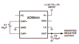
The ADM660 is a charge-pump voltage converter that can either invert the input supply voltage or double it. The schematic below depicts the ADM660 Voltage Inverter Circuit Configuration Diagram. This inverting schematic is ideal for generating a negative rail...