
DC generator automatic voltage regulator circuit

The DC generator automatic voltage regulator circuit is a critical component in maintaining stable output voltage in a 40kW, 230V DC shunt complex machine. The circuit operates by monitoring the output voltage and making necessary adjustments to ensure that it remains within specified limits, with a voltage change rate of no more than 2.5 percent.
In the schematic, the shunt winding (BQ) is connected to the generator's output terminals, which allows it to sense the voltage level. The series winding (co) is incorporated into the circuit along with an external shunt resistor (Rw), which is essential for controlling the overall voltage feedback loop. The presence of the series winding aids in improving the response time of the voltage regulation, especially during load variations.
The adjustment potentiometer (RP) plays an important role in the regulation process. By varying the resistance through this potentiometer, the operator can set the desired output voltage level. This capability is particularly useful during initial setup or when the load conditions change significantly, allowing for fine-tuning of the generator's performance.
Overall, this automatic voltage regulator circuit is an essential feature for ensuring the reliable operation of the DC generator, providing both stability and flexibility in voltage management for various applications.DC generator automatic voltage regulator circuit is shown in Figure 7-53. This circuit is used to 40kW, 230V DC shunt complex machine, the voltage change rate up to 2.5 percent . In Figure 7-53, BQ for the shunt winding, co} for the series winding in series with the external shunt resistor Rw winding circuit. Adjustment potentiometer RP, can change the generator output voltage setpoint.
Related Circuits

This circuit represents a waveform generator, which is highly beneficial for electronic experiments and design. It primarily generates sine wave oscillations, but the circuit can be modified to produce triangle or square wave functions. The circuit is based on...
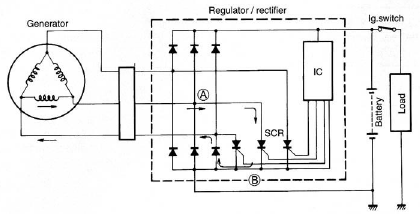
The circuit of the Suzuki GSX1300 Hayabusa charging system consists of a generator, a regulator/rectifier unit, and a battery. The alternating current (AC) generated by the generator is rectified by the rectifier to produce direct current (DC), which is...
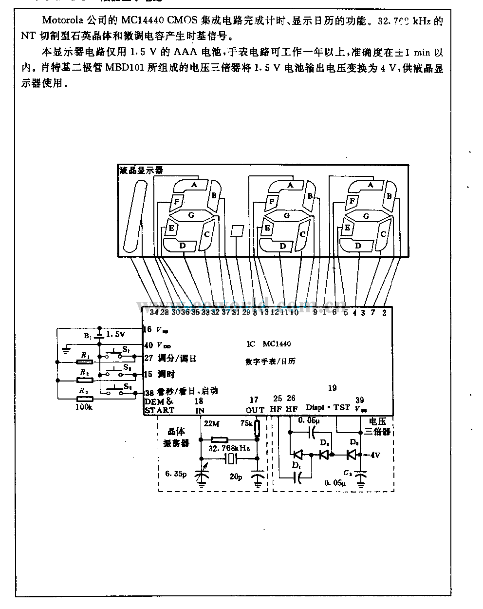
The Motorola company's MC14440 CMOS integrated circuit is designed for timing and displaying calendar functions. It utilizes a 32.768 kHz NT cutting type quartz crystal along with fine-tune capacitance to generate time-based signals. The display circuit operates on a...
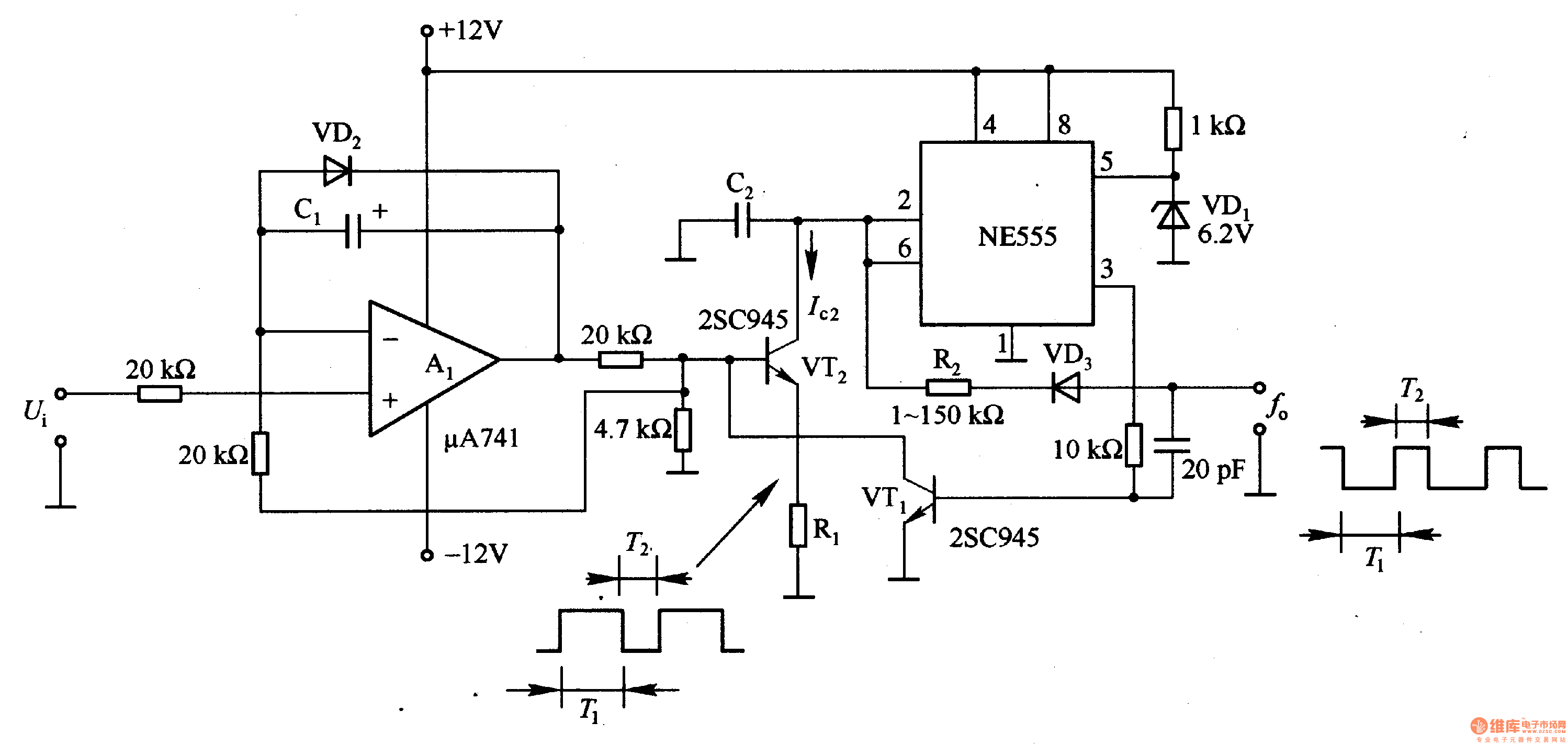
In the circuit, the oscillation frequency of the NE555 is controlled by VT2. When the output at pin 3 is low (during the T1 period), VT1 stops conducting, and VT2 begins to conduct with a current Ic2 flowing through...
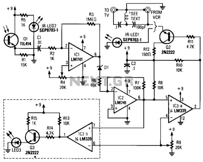
A signal from an infrared (IR) remote control is converted from IR radiation to a frequency pulse that can be transmitted through coaxial TV cable or any other two-conductor wire to another room, where it is converted back into...
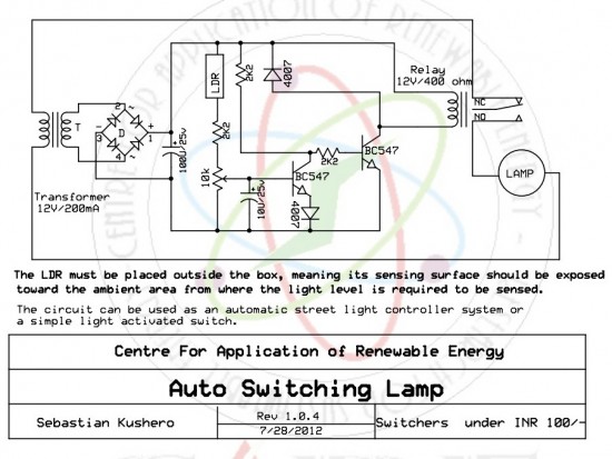
The circuit is designed to switch off a specific lamp or a group of lamps based on varying ambient light levels. Once constructed, it will turn off a lamp at dawn and turn it on at dusk. The power...