
dc motor 12v speed controller circuit

The described encoder circuit for a DC motor utilizes the HA-2542 operational amplifier to achieve effective speed control. The core functionality revolves around the position encoder, which outputs a series of pulses corresponding to the motor's rotational position. Each pulse indicates a specific increment of movement, allowing for precise speed measurement and control.
In the configuration, capacitor C1 serves as a charge storage component, integrating the pulse signals from the encoder. The reference voltage generated is directly proportional to the motor's speed, thus enabling real-time feedback for the control system. The HA-2542 operational amplifier is configured in a differential mode, where the inverting input receives the integrated pulse signal, while the non-inverting input is set to a predetermined voltage that signifies the target speed. This setup facilitates the comparison of actual speed against the desired speed.
If a discrepancy exists between the actual speed (inverting input) and the desired speed (non-inverting input), the operational amplifier outputs a corrective signal. This signal adjusts the power supplied to the DC motor, ensuring that it accelerates or decelerates to match the set speed. The simplicity of the circuit design, with minimal external components, enhances its reliability and ease of implementation.
The limitation mentioned regarding the encoder wheel can be mitigated by incorporating a pulley system. By attaching a pulley to the encoder wheel, the motor can be connected to another device via a belt. This allows the speed control system to influence the operation of additional machinery, effectively expanding the circuit's application beyond a single motor. This versatility makes the encoder circuit suitable for various automation and control projects, where precise speed regulation is essential.A very simple encoder circuit for a dc motor can be constructed using this circuit diagram. As you can see in the circuit diagram, the system shown consists of the HA-2542, a small 12-Vdc motor, and a position encoder. During operation, the encoder causes a series of constant-width" pulses to charge CI. The integrated pulses develop a reference voltage, which is propor £ional to motor speed and is applied to the inverting input of HA-2542, The noninverting input is held at a constant voltage, which represents the desired motor speed. A difference between these two inputs will send a corrected drive signal to the motor, which completes the speed control system loop.
As you can see the circuit requires few external components, but because of the encoder wheel it has a limitations of use. If you put a pulley under the encoder wheel you can command the speed of other device, by connecting the (motor and other device ) using a belt
🔗 External reference
Related Circuits
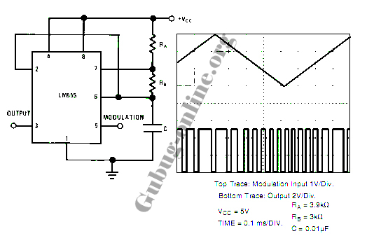
This design circuit for a pulse position modulator can be easily constructed using a 555 integrated circuit (IC). The pulse position modulator modulates the on-period while maintaining a fixed off-period. The circuit utilizes the 555 timer IC in astable mode...
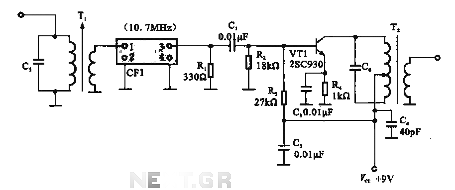
This circuit features a ceramic filter integrated with an FM intermediate frequency (IF) amplifier. The FM IF amplifier circuit primarily consists of an input variable voltage regulator (T), ceramic filters (CF1), and additional components such as the IF amplifier...
A schematic of a flip-flop LED flashing circuit is presented. This circuit functions as an astable multivibrator that activates LEDs sequentially upon power application. It is compatible with voltage inputs ranging from 6 to 12 volts, and can also...

The following circuit illustrates a simple 100W inverter circuit diagram. This circuit is based on the CD4047 integrated circuit (IC). Features include low power CMOS technology. The simple 100W inverter circuit utilizes the CD4047 IC, which is a versatile device...
The output current of the control circuit must be amplified when the gate current needed to trigger the device exceeds the output current of the control circuit. To achieve the amplification of the control circuit output current, a suitable transistor...
The human approach detector circuit consists of an integrated operational amplifier, a gate circuit, and a resistor-capacitor unit as illustrated in the diagram. The 1 MHz oscillator is composed of a reverser T1, a 1 MHz crystal oscillator, and...