
Pulse Position Modulator Circuit

The circuit utilizes the 555 timer IC in astable mode to generate a series of pulse signals. In this configuration, the timing components, namely resistors and capacitors, determine the frequency and duty cycle of the output waveform. The output frequency can be adjusted by varying the values of these components, enabling the modulation of the pulse width.
In pulse position modulation (PPM), the position of the pulse is varied while keeping the duration of the off-period constant. This technique is particularly useful in applications such as remote control systems and communication devices, where the timing of the signal can convey information.
The 555 timer operates by charging and discharging a timing capacitor through the resistors connected to its discharge and threshold pins. The output pin generates a square wave, which can be further processed to achieve the desired modulation characteristics. By implementing additional circuitry, such as filters or amplifiers, the PPM signal can be refined for specific applications.
In summary, this circuit design offers a straightforward approach to creating a pulse position modulator using the versatile 555 timer IC, providing a reliable method for signal modulation in various electronic applications.Here s the design circuit for pulse position modulator can be easily built using 555 IC. Here s the figure of the circuit; .Pulse position modulator modulate the on-period while keeping the fixed off-period. Pulse position modulation might subs .. 🔗 External reference
Related Circuits

A series of LEDs that turn on and off in a precise sequence, creating a calming and hypnotic effect. Various LED chaser, scanner, and sequencer circuits exist, utilizing discrete transistors, logic integrated circuits (ICs), or microcontrollers. However, a common...
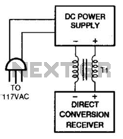
One solution for AC power line hum and ripple, which is caused by leakage current, is to utilize a well-regulated and filtered 9 to 18 VDC power supply that incorporates a balancing choke (Tl in this illustration) between the...
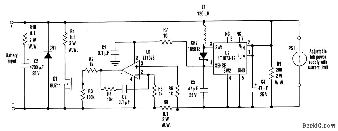
When developing a battery charger, using a real battery can be impractical. The battery simulator circuit described here serves as an alternative. The positive and negative terminals of the battery input should be connected in place of the actual...
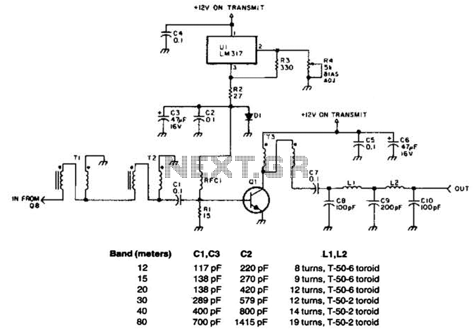
This linear amplifier provides a 10-W PEP output with a 1.25-W drive on the 10 m band. The transformers, T1, T2, and T3, consist of 10 turns of bifilar windings on an FT-50-43 toroidal core and are designed for...
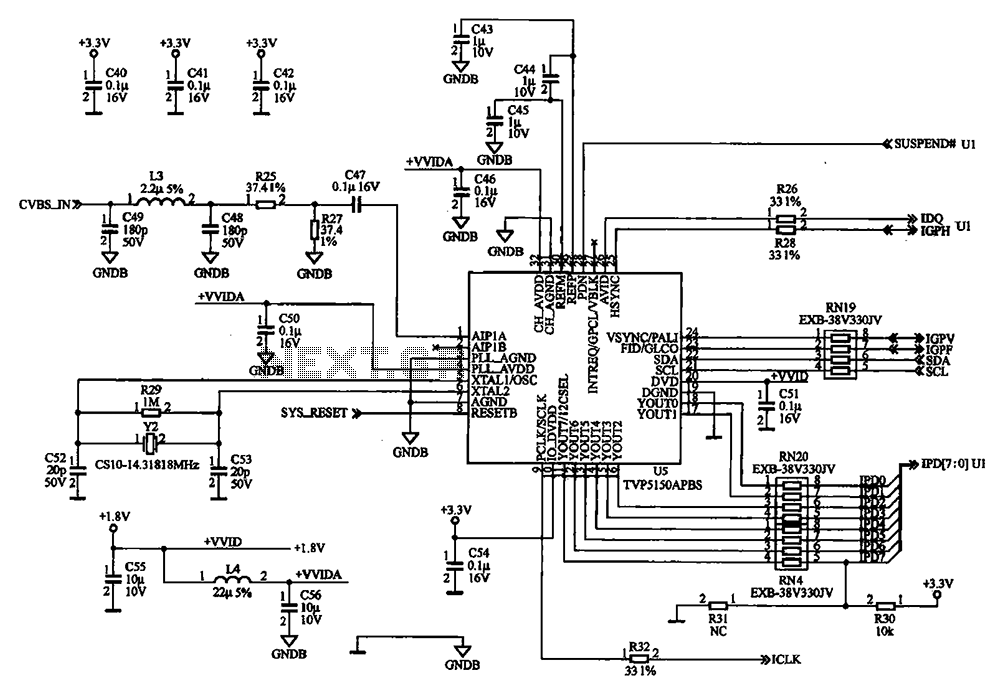
The external audio spectrum display circuit is designed for high-end audio equipment, providing both real-time playback signal analysis and visually appealing effects. This display does not require any electrical connections to the sound equipment; it can simply be placed...
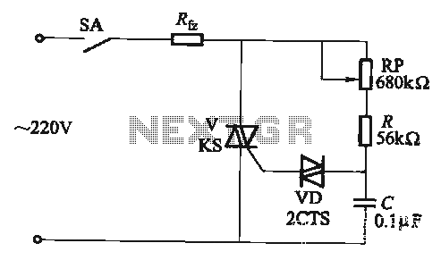
The adjustment potentiometer RP allows for the modification of the TRIAC conduction angle, facilitating temperature control applications. The adjustment potentiometer (RP) serves a crucial role in controlling the conduction angle of the TRIAC, which in turn regulates the power delivered...