
Dc motor speed control 2

Power operational amplifiers are integral components in circuits designed for the precise control of DC motor speed. This specific circuit configuration allows for bidirectional control, enabling the motor to rotate in both clockwise and counterclockwise directions. The push-pull configuration of the operational amplifiers is critical, as it allows for a full rail-to-rail voltage swing across the motor terminals, ensuring that the motor receives adequate power for efficient operation in either direction, while taking into account the output stage saturation drops.
The inclusion of a mechanically-coupled tachometer serves a pivotal role in maintaining speed stability. The tachometer generates feedback that is fed into the first amplifier section, allowing for real-time adjustments to the motor's speed based on its current performance. This feedback loop is essential for achieving consistent motor operation, particularly in applications where speed variations can lead to performance issues.
The adjustment of the motor's speed and direction is facilitated by a 10 kΩ potentiometer connected to the non-inverting input of the operational amplifier. This potentiometer allows for fine-tuning of the input signal, thereby directly influencing the output voltage and, consequently, the speed and direction of the motor.
To ensure the stability of the control loop, an RFCF feedback network is employed. This network is designed to prevent oscillations that can arise due to the dynamic mechanical lag inherent in motor systems. The selection of the RFCF time constant is crucial, as it must be tailored to match the specific characteristics of the motor being used. By doing so, the circuit can effectively compensate for delays in response, ensuring smooth and stable operation across a range of operating conditions.Power op amps provide accurate speed control for dc motors. The circuit provides bidirectional speed control. The amplifiers' push-pull configuration ensures a full rail-to-rail voltage swing (minus the output stages' saturation drops) across the motor in either direction. The circuit uses a mechanically-coupled tachometer to provide speed-stabilizing feedback to the first amplifier section.
The motor's speed and direction of rotation is set by adjusting the 10 k ohm potentiometer at the amplifier's noninverting input. The RFCF feedback network prevents oscillation by compensating for the inherent dynamic mechanical lag of the motor.
Select the RFCF time constant to match the particular motor's characteristics.
Related Circuits
This circuit is a stable frequency counter with an accuracy of 5 significant digits. It operates within a frequency range of 0 to 30 MHz and has an input sensitivity greater than 100 mV. The probe connects to the...
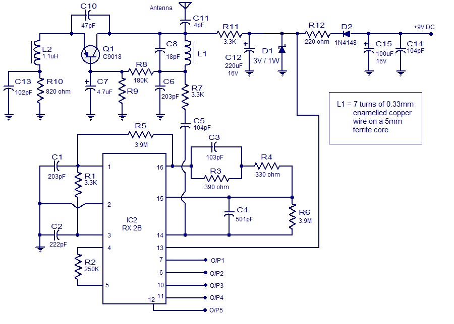
This article discusses a simple five-channel radio remote control circuit utilizing the TX-2B and RX-2B integrated circuits from Silan Semiconductors. The TX-2B/RX-2B is a remote encoder-decoder pair suitable for remote control applications. It features five channels, a wide operating...
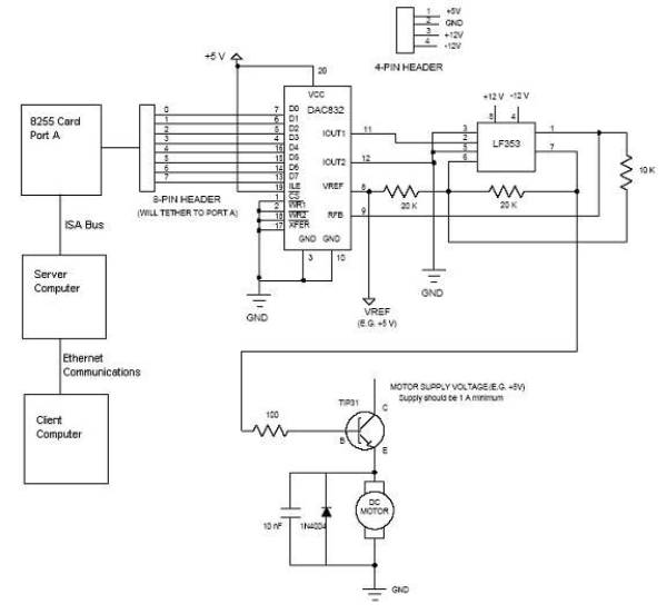
Open loop speed control of a DC motor is implemented using the 8255 Digital I/O Controller chip in conjunction with a TCP/IP server-client application programmed in Visual Basic. The DAC0832 chip serves as the Digital to Analog Converter. This...
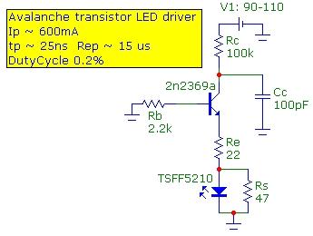
The speed of light has been measured using various methods. This note describes a method that is conceptually easy to understand and relatively simple to implement. The technique utilizes the time-of-flight optical pulse delay method, employing a short (20...
AutoZone Repair Guide for Driveability and Emission Controls, focusing on Evaporative Emission Controls. The AutoZone Repair Guide provides comprehensive information regarding driveability and emission control systems, with a specific emphasis on evaporative emission controls. These systems are crucial for reducing...
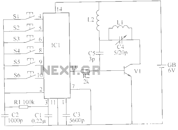
This example describes a wireless remote control switch featuring reliable operation and practical characteristics, capable of remotely controlling a 6-channel device within a 6-meter range for household electricity. The wireless remote control switch circuit consists of a wireless transmitter...