
6m wireless remote control switch circuit

The wireless remote control switch is designed to facilitate the operation of multiple electrical devices from a distance, enhancing convenience and functionality in a household setting. The wireless transmitter section utilizes an integrated circuit (IC1) to encode signals from the control buttons (S1 to S6). Each button corresponds to a specific channel, allowing the user to selectively activate or deactivate connected devices.
The transmitter circuit includes a power supply unit, typically a battery (GB), which powers the entire system. Resistors (R1, R2) are employed for current limiting and voltage division, ensuring that the circuit operates within safe parameters. The inductors (L1, L2) may be used for filtering or tuning purposes, optimizing the signal transmission and reception.
The receiver circuit, which is not detailed in the initial description, is equally important as it decodes the signals sent from the transmitter. Upon receiving a signal, the receiver activates the corresponding output channel, which may be connected to a relay or a solid-state switch, allowing the control of high-voltage devices safely.
The operational range of 6 meters is typical for such wireless systems, achieved through careful selection of components and circuit design. The overall architecture of the wireless remote control switch circuit is compact and efficient, making it suitable for various applications around the home, such as controlling lights, fans, or other electrical appliances. The simplicity of the design ensures ease of use and installation, making it accessible for both amateur and professional electronics enthusiasts.This example describes a wireless remote control switch, with reliable operation, simple and practical features, can remote control 6-channel device in the 6m range of household electricity. The wireless remote control switch circuit by the wireless transmitter and wireless receiver circuit control circuit. Encoded by a wireless transmitter integrated circuit IC1, the control button S1 ~ S6, the transistor V1, resistors R1, R2, inductors L1, L2, and capacitors C1 ~ C5 battery GB, as shown in Fig.
Related Circuits
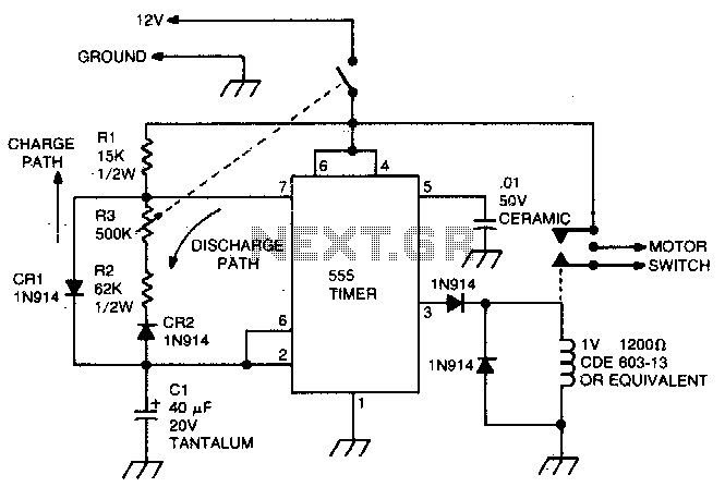
This circuit utilizes the 555 timer in astable or oscillatory mode. The duration for which the timer remains off is determined by the values of capacitor C1, resistor R2, and resistor R3. A potentiometer is incorporated to adjust the...
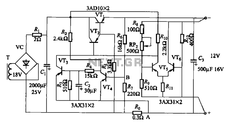
The circuit features a current protection mechanism utilizing transistors VTa, VT4, and a sense resistor Ro. When an overcurrent or short-circuit fault occurs, the power supply cannot resume normal operation because the conduction condition of VT3 remains unchanged, resulting...
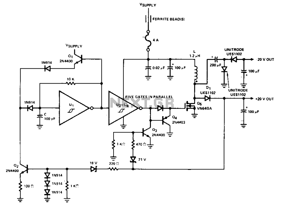
This PWM control circuit generates control pulses for the DMOS power switch in the flyback circuit. The PWM output produces a pulse width that is proportional to the input control voltage, with the repetition rate governed by an external...
This circuit operates at potentially lethal 220V AC mains voltage. The circuit should be built and used only by individuals who know how to safely work with such dangerous voltages and how to construct the circuit to ensure safety....
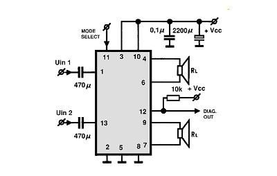
A simple Class B power amplifier can be constructed using the TDA8560 audio integrated circuit (IC). The TDA8560 amplifier features an internally fixed voltage gain, ensuring excellent channel balance. This audio amplifier project is capable of delivering dual 40-watt...
The circuit consists of a lag comparator with amplifier A1 and an inverting integrator A2. The charging and discharging time constant is determined by the integral resistors (R1 + RP1) and the capacitor C1. Diodes VD1 to VD5 form...