
DC motor speed control circuit diagram of a song

The circuit employs a rectifier bridge configuration (G1) to convert AC voltage from the transformer’s secondary winding into a usable DC voltage for the motor. This rectification process is crucial for providing a steady and reliable power supply to the motor, which is essential for consistent speed control. The control mechanism is further enhanced by the use of a sliding contact potentiometer (Rp), which functions as a variable resistor. Adjusting the position of the sliding contact alters the resistance in the circuit, thereby modifying the voltage supplied to the motor.
When the sliding contact is positioned at the midpoint, the circuit effectively disconnects the motor, stopping its operation. This feature serves as a safety mechanism, preventing unintended motor activation. Conversely, moving the sliding contact in either direction allows for the adjustment of motor speed and direction. The upward movement increases the voltage, causing the motor to rotate in the forward direction, while downward movement decreases the voltage, reversing the motor's rotation.
In practical applications, this circuit can be implemented in various settings, including robotics, conveyor systems, and other automated machinery where precise motor control is necessary. The design ensures that operators can easily manage the motor's performance, providing flexibility and adaptability to different operational requirements. Overall, this circuit represents a robust solution for controlling low-power DC motors with both speed and directional capabilities, making it a valuable component in electronic control systems. Circuit can be used to control low power DC motor, series motor or shunt motor speed and direction. Motor and rectifier bridge G1 series, and then connected to the grid transfo rmer secondary winding n2. If the output of the rectifier bridge fails, the motor stops, which is equivalent to the sliding contact potentiometer Rp in the middle position, if the upward or downward movement of the sliding contact, the motor will forward or reverse, it can control the motor operation.
Related Circuits
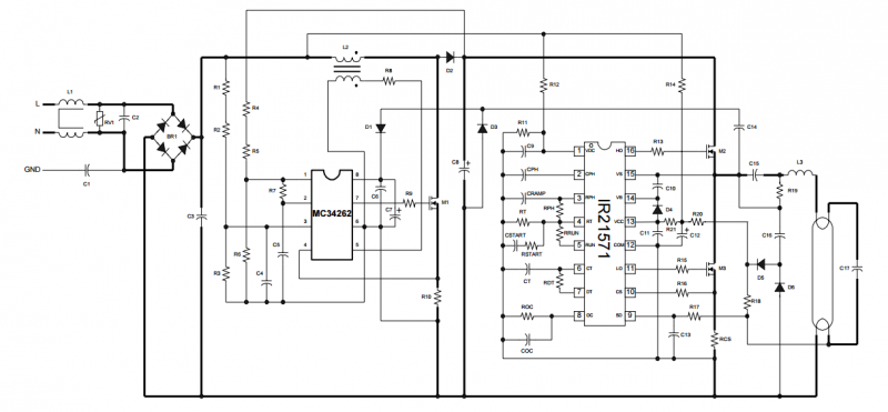
The IRPLLNR2 is a high efficiency, high power factor, fixed output electronic ballast designed for driving rapid start fluorescent lamp types. The design contains an EMI filter, active power factor correction and a ballast control circuit using the IR21571....
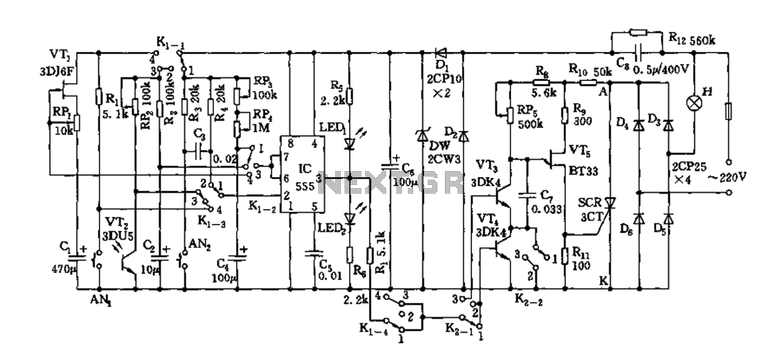
Depending on the external circuit connection, the 555 timer can be configured for various modes such as start delay, trigger delay, multi-harmonic oscillation, and other operational conditions. It functions as a versatile tester with the inclusion of some RC...

A series of LEDs is used to alert the gardener when plants require watering. By utilizing two conventional digital integrated LEDs along with a series of additional LEDs, this device serves as a practical tool for gardening. It detects...
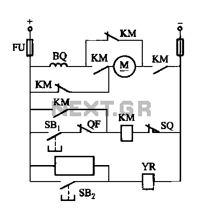
The DW16M-630 type excitation switch operates with both DC and AC power. The circuit for DC operation is illustrated in Figure 7-60, while the circuit for AC operation is shown in Figure 7-61. The BQ single-phase series motor M...

This is an application circuit for calibration known as a high voltage AC calibrator circuit. An essential aspect of sine wave oscillator design is the stable control of amplitude. This circuit not only stabilizes the amplitude through servo control...
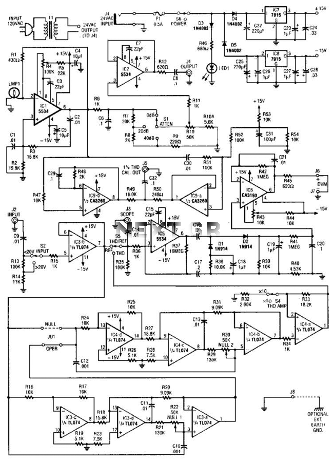
The circuit comprises a low-distortion, 1-kHz oscillator designed to measure Total Harmonic Distortion (THD) at a user-selected voltage level, suitable for voltage amplifiers or for testing amplifiers with power levels up to 600 W. It is capable of detecting...