
DW16M-630 type DC excitation switch control circuit

The DW16M-630 excitation switch is designed to facilitate the control and management of electrical circuits in both direct current (DC) and alternating current (AC) applications. The DC circuit configuration, as depicted in Figure 7-60, typically includes components such as a power source, the excitation switch, and load elements that are optimized for steady-state performance. The operational characteristics of the DC circuit ensure that the excitation switch can effectively manage the power flow, providing reliable and consistent operation for connected devices.
In contrast, the AC circuit configuration shown in Figure 7-61 incorporates various components that cater to the unique characteristics of alternating current. The BQ single-phase series motor M is a critical element, featuring a series winding that enhances its performance by allowing for efficient torque generation. The terminal switch connects the motor to the excitation switch, enabling seamless operation.
The closing contactor, represented by KM, plays a vital role in controlling the power supply to the motor. When activated, it establishes a connection that allows current to flow to the motor, initiating its operation. The resistance component, denoted as R, is used to limit the current and protect the circuit from overloads, ensuring the longevity of the system.
The trip coil, represented by YR, serves as a shunt release mechanism that can quickly disconnect the circuit in the event of an overload or fault condition. This feature enhances the safety of the system by preventing potential damage to the components. Additionally, the QF export circuit breaker includes a normally closed auxiliary contact, which provides an extra layer of protection by ensuring that the circuit remains closed until a fault is detected, at which point it will open to interrupt the current flow.
Overall, the DW16M-630 excitation switch is an essential component in managing both DC and AC powered systems, providing flexibility and reliability in various applications. Its design incorporates key safety features and operational controls that enhance the performance and protection of electrical circuits.DW16M-630 type excitation switch operation with DC power and AC power operation of the two, the former circuit is shown in 7-60 J, the latter circuit shown in Figure 7-61: figu re, BQ single-phase series motor M the series winding, so the terminal switch. KM is closing contactor, R is the resistance. YR for the trip coil (shunt release), QF export circuit breaker normally closed auxiliary contact.
Related Circuits
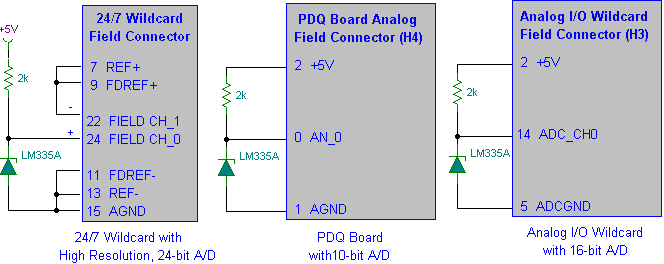
Interfacing the LM335A temperature sensor with A/D converters involves measuring temperature using the LM35 and LM335A sensors alongside the 9S12 HCS12 microcontroller. This process includes analyzing both calibrated and uncalibrated temperature errors of integrated circuit temperature sensors. The LM335A is...
To complement the 60 Watt MOSFET audio amplifier, a high-quality preamplifier design was necessary. A discrete components topology using +24V and -24V supply rails was chosen, minimizing the transistor count while still achieving low noise, very low distortion, and...
This project describes a new economical solution of home light control systems. The presented home light control system can be used for different sophisticated home applications. The control system consists of a PC, and control circuitry and the electrical...
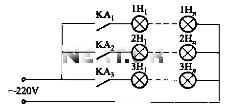
The relay control system utilizes multiple pairs of contacts, allowing for the connection of higher power lamps in parallel. The circuit design is straightforward; by altering the capacitance of the capacitor, different flashing frequencies can be achieved. The described circuit...
The output voltage is = 0.707 x Vin, at the center position. The output voltage is = Vin, at either extreme position. This circuit appears to describe a variable output voltage system, likely utilizing a potentiometer or a similar adjustable...

This design outlines a simple wideband output amplifier suitable for use as a 50-ohm transmission line driver. The circuit is constructed using the CA3140 operational amplifier. When utilized alongside the function generator and sine wave shaper circuits, it delivers...