
DC motor speed control using 8051 and l298

The AT89C55WD microcontroller is an 8-bit microcontroller from the 8051 family, featuring a 40-pin dual in-line package (DIP) design. It is equipped with 32 I/O lines, two 16-bit timers/counters, and a full-duplex UART for serial communication. This microcontroller is well-suited for applications requiring precise control and interfacing with various peripherals.
In this application, the AT89C55WD interfaces with an L298 H-Bridge driver. The L298 is a dual H-Bridge motor driver capable of driving two DC motors or one stepper motor. The H-Bridge configuration allows for bidirectional control of the motors, enabling forward and reverse operation. The L298 can handle up to 2A of continuous current per channel and is suitable for motors operating at voltages ranging from 5V to 46V.
The circuit design involves connecting the output pins of the AT89C55WD to the input pins of the L298. Typically, four control pins are used to manage the two motors: two for each motor's direction and two for enabling the motors. PWM (Pulse Width Modulation) signals can be generated by the microcontroller to control the speed of the DC motors by varying the duty cycle of the signals sent to the enable pins of the L298.
Power supply considerations are critical in this setup. The microcontroller should be powered with a stable voltage, typically 5V, while the L298 should be connected to a suitable power source that matches the motor's voltage requirements. It is also advisable to include decoupling capacitors near the power pins of both the microcontroller and the L298 to filter out noise and ensure stable operation.
In summary, this configuration leverages the AT89C55WD microcontroller's capabilities to control an L298 H-Bridge driver, allowing for effective management of DC motors in various applications, including robotics and automation systems. Proper circuit design and component selection are essential for achieving reliable performance in the intended application.Hi Everyone out there! I am new to microcontrollers. I am using AT89C55WD to control H-Bridge (L298) which in turn drives the DC motor. Circuits for.. 🔗 External reference
Related Circuits
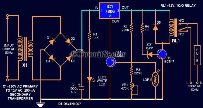
This circuit automates the control of street or porch lights. The automatic lamp controller circuit utilizes a 7806 voltage regulator IC, which can be employed to automate street lights, tube lights, or any other home electrical lighting systems. The...
An operational amplifier such as the NE5532 should be used. The desired frequency must be calculated for each block: one for flat, one for bass, and one for high frequencies. It is important to include a buffer at the...
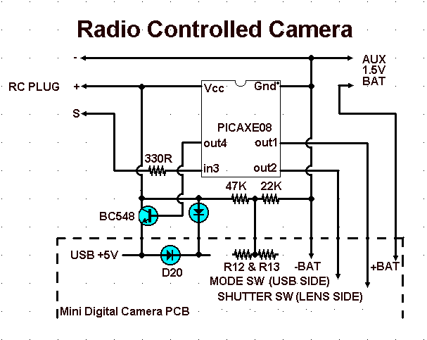
The aim of this project was to get a digital camera into a small electric radio controlled (RC) aeroplane and still have it fly. The aeroplane shown, a park flyer, weighs between 400 and 550 grams depending on the...
A project is underway to control the speed of an electric fan (220Vac, 60W, 5A max.) automatically using a microcontroller based on certain parameters. The circuit design for controlling the speed of an electric fan involves several key components to...
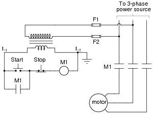
The most challenging aspect of interpreting ladder diagrams, particularly for individuals familiar with electronic schematic diagrams, is the representation of electromechanical relays. The operation of a motor control circuit should be explained, detailing what occurs when the "Run" switch...

The main oscillator is printed in blue and is voltage controlled. In this construction, the VCO range is 88 to 108 MHz. As you can see from the blue arrows, some energy goes to an amplifier and some energy...