
Automatic Light Controller Using 7806 And LDR PCB

The circuit design comprises several key components that work together to achieve automatic lighting control. The 7806 voltage regulator IC is pivotal in maintaining a constant voltage output, ensuring that the connected devices receive a stable power supply regardless of fluctuations in the input voltage. This feature is particularly useful in outdoor lighting applications where voltage stability is crucial for reliable operation.
The BC557 transistor serves as a switch in the circuit. Its base is connected to the LDR, which changes resistance based on the ambient light conditions. When the light level drops below a certain threshold, the resistance of the LDR increases, allowing the transistor to turn on. This activation of the transistor enables the current to flow from the 7806 output, which in turn energizes the relay connected to the lighting system.
The adjustable sensitivity of the light control is facilitated by the variable resistor (VR1). This component allows users to set the desired light level at which the circuit will activate the relay. By tuning VR1, the responsiveness of the circuit to light changes can be optimized for different environments or user preferences.
In nighttime conditions, as the ambient light diminishes, the LDR's resistance increases, triggering the BC557 transistor to conduct. The output voltage from the 7806 then rises to the input voltage level, which is sufficient to energize the relay. This action closes the relay contacts, allowing power to flow to the connected lighting system, thereby illuminating the area as intended.
Overall, this automatic lamp controller circuit is a practical solution for efficient outdoor lighting management, providing convenience and energy savings by ensuring that lights are only activated when necessary.This circuit controls the switching of the street light or porch light and it will be automated. This circuit of automatic lamp controller using 7806 regulator ic can be used to automate street lights, tube lights or any other house electrical lightning systems. the IC 7806 is a voltage regulator ic that give a steady output voltage against widely fluctuating dc input voltage. For this IC, any voltage that appears in common terminal will be reflected at the output. So when the ground terminal is disconnected, the input is available at the output. By the way the circuit is self explanatory, i will give you a simple description. The 7806 common terminal is driven by a BC557 transistor. for automatic light control, the base of this transistor is connected through a LDR In this way, the voltage regulator is able to operate a light bulb automatically as per the ambient light. The light sensing level can be adjusted by using VR1 preset. During day time, the transistor T1 will be on and the IC1 output will be 6V that is not much to energize the relay.
During night the 7806 output will be the input voltage and the relay become energized. 🔗 External reference
Related Circuits
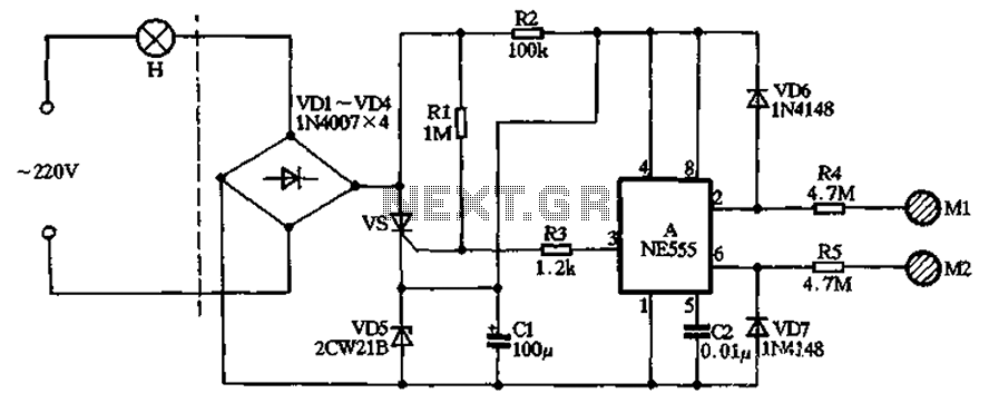
The circuit illustrated in the figure features a dashed line on the left, representing a standard lighting circuit, while the right side is responsible for the dual functionality of touch activation using the NE555 timer. Components VD1 through VD4...
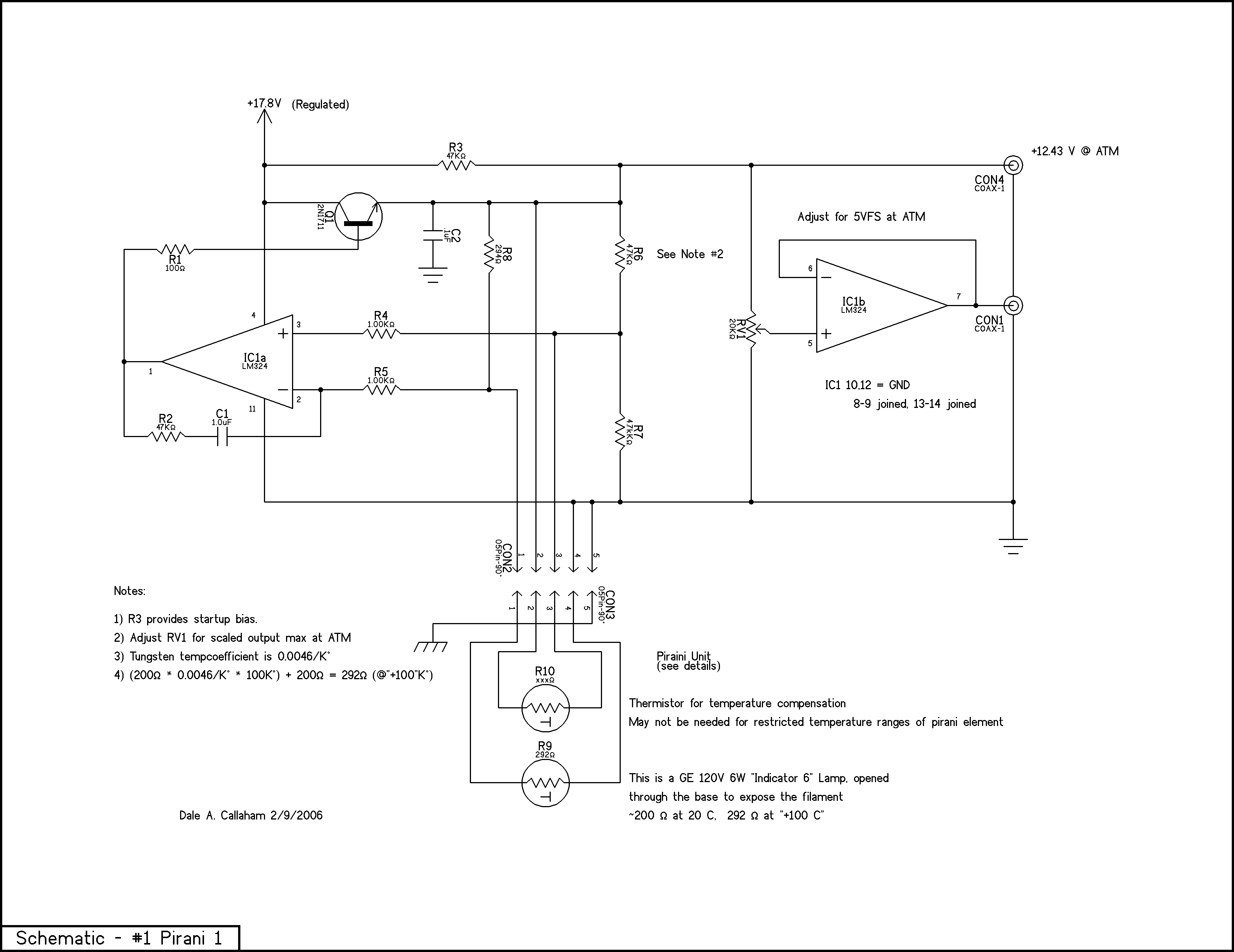
The principle is that the resistance of metals increases at higher temperatures, and a heated wire suspended in a gas will lose heat by conduction and convection in proportion to the number of gas molecules present; thus, the heat...

A prerequisite for this article is that the GCC AVR programming environment is installed as described in the article "Programming the AVR microcontroller with GCC, libc 1.0.4." To avoid installation issues, using the AVR programming CD is recommended. When...
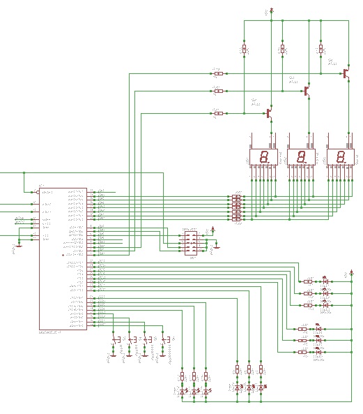
Learn to use microcontrollers to create traffic-light applications. In this project, the AVR-007 microcontroller from Circuits-Home will be utilized. Before developing the program, it is essential to understand the hardware specifications. The project focuses on developing a traffic-light control system...
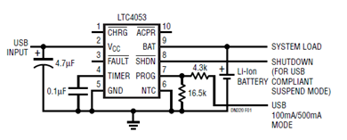
The schematic presented illustrates a minimal component solution for a USB battery charger utilizing the LTC4053 integrated circuit (IC) to create a fully compliant USB charger. This IC functions as a standalone linear charger designed for lithium-ion (Li-ion) batteries,...
Using high-beam headlights while driving on the highway can significantly enhance visibility; however, they may pose a blinding risk to other drivers. This straightforward circuit can be integrated into the headlight switch to enable automatic switching between high and...