
DC relay circuits to delay the release of a second

The relay circuit described involves a relay coil that is critical for controlling larger loads with a smaller control signal. The inclusion of a resistor (Rf) or an auxiliary diode (VD) serves to manage the current flow and protect the circuit from back EMF generated when the relay is deactivated. When the relay coil is energized, the magnetic field builds up, allowing the relay contacts to close and complete the circuit for the load.
If a resistor Rf is used in parallel with the coil, it provides a path for the current to continue flowing even after the control signal is removed, thereby prolonging the magnetic field and allowing for a slower release of the relay contacts. This can be beneficial in applications where a quick drop in power could cause issues, such as in motor control or in systems requiring a gradual disengagement.
On the other hand, when an auxiliary diode (VD) is employed, it serves as a flyback diode. This diode allows the current generated by the collapsing magnetic field to safely dissipate, protecting the circuit components from voltage spikes that could otherwise cause damage. The absence of Rf in Figure 6-24(b) indicates a direct connection of the relay coil to the control signal, which may result in a more immediate release of the relay contacts when the control signal is removed.
In summary, the choice between using a resistor or a diode in parallel with a relay coil significantly influences the behavior of the relay in terms of release time and circuit protection. Proper selection based on the specific application requirements is essential for reliable circuit operation.Circuit shown in Figure 6-24. Both ends of the relay coil ' in parallel with a resistor Rf or auxiliary diode VD, is equivalent to power after a short circuit coil core increase, thus making prolonged release. Figure 6-24 (b) of Rf can not.
Related Circuits
The LED flasher circuits below operate on a single 1.5 volt battery. The circuit on the upper right uses the popular LM3909 LED flasher IC and requires only a timing capacitor and LED. The top left circuit, designed by...
Building circuits to interface an Amiga A1200 to a PC AT/ATX power supply and tower case. To create a reliable interface between an Amiga A1200 and a PC AT/ATX power supply and tower case, it is essential to design a...
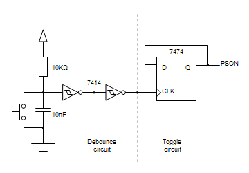
This toggle circuit operates by using a couple 555 timers wired as inverters. Pins 2 and 6 are the threshold and trigger inputs to the first timer and pin 5 is the output. The output at pin 5 will...

This topic will be locked and will display all of the circuits and some photos of the devices being worked on in the Joule Thief topic. This process will take some time, so patience is appreciated. If any errors...
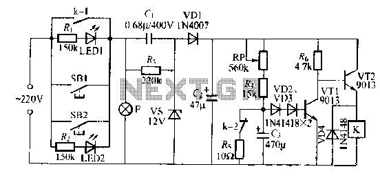
The lamp relay delay circuit is illustrated in Figure 7. Components S131 and SB2 are light buttons mounted in different locations. The lamp can operate with F. LEDs (LED1 and LED2) should be installed in SB1 and SB2 to...
The fundamental issue presented is the perception that logic gates in a circuit seem to generate power from nothing, which contradicts the principles of physics. For instance, consider two NOT gates connected in series. It appears that the first...