
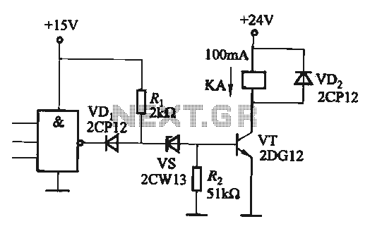
Lamp relay delay circuit

The lamp relay delay circuit operates based on a combination of resistive and capacitive components that establish a time delay for the activation and deactivation of the lamp. The circuit's design incorporates a step-down regulator that converts higher voltage inputs into a stable 12V DC output, essential for the reliable operation of the relay and associated components. The use of LEDs for switch position indication enhances user interaction by providing visual feedback regarding the circuit's state.
The relay employed in this design, the JRX-13F, is particularly suited for applications requiring compact size and reliable operation. Its two changeover contacts allow for versatile circuit configurations, enabling the design to accommodate various load requirements. The interaction between the relay and the capacitors is critical; as the capacitors charge, they create a delay in the relay's response, allowing for controlled operation of the lamp. The adjustment of the resistor RP allows for fine-tuning of the delay time, providing flexibility in the circuit's performance based on specific application needs.
Overall, this circuit exemplifies a practical application of electronic components to achieve a desired functionality, demonstrating the principles of relay operation, voltage regulation, and delay mechanisms effectively.Lamp relay delay circuit shown in Figure 7], S131, SB2 are lights button mounted anti-machi not a different place, the lamp can operate F. LEDs LEDl, LFr) 2 should be installed in SB1 and SB2 at the "Peter asked in switch position indication easy to use.
When the lights required, just press the SB1, SB7 any one towel a lamp E on the light-emitting. LEDI, LED2 goes off. and the same time at both ends of the lamp post .1 NIE galvanic suffer through (J, c ,, VS, VD1 and other simple electrical composed of step-down regulator rectifier circuit, in (Both ends of the steady output of about 1 2V given DC voltage. Since the feet. RP resistance is much less than ten Torr, VT1 off, VT2 conduction, so the relay K station, station electric shock kl closing station, the circuit self-locking.
At the same time, jump off contact k2 Since two capacitors G J terminal voltage can not mutation, VTI remains off state so that a lamp F may continue to emit light. then, 12V DC by the RP, R to allow electricity to make (1 Galvanic callosum constantly J high, when rose 3 0 65V just, VD2, VD3 and are conduction VT1, VT2 off energized relay K release, its contact kl, k2 reset, turn off the lamp F, called with LED1, LED2 and light indication switch position.
trimming pruning when the resistor RP coup lights can delay l Division, K called using JRX-13F, DClZV other small type electromagnetic relay which has two changeover contacts, can be full enough Bong circuit requirements.
Related Circuits
If the CMOS circuit load (actuator) is a relay device, the circuit must have a large load capacity. Non-gate drive switching amplifiers are connected to a separate element shown in the interface circuit. In the context of a CMOS circuit...
NE5532DR absolute maximum ratings: (1) Supply voltage: VCC+ 22 V; VCC-: -22 V; (2) Input voltage, either input VCC ±; (3) Input current: ±10 mA; (4) Duration of output short circuit: Unlimited; (5) Package thermal impedance, JA: D package...
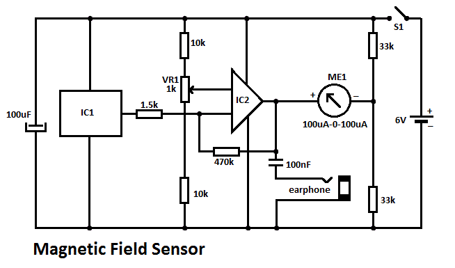
This DIY magnetic field sensor circuit is straightforward and capable of detecting both static magnetic fields and those that vary at audio frequencies. The unit is designed to be user-friendly and efficient. The magnetic field sensor circuit typically employs a...
National Semiconductor (NS Company) produces audio integrated circuits (ICs) that offer wide frequency response and low noise. These circuits provide excellent performance across all NS products. The circuit illustrated in Figure 3-12 includes a preamplifier and a singing equalizer...
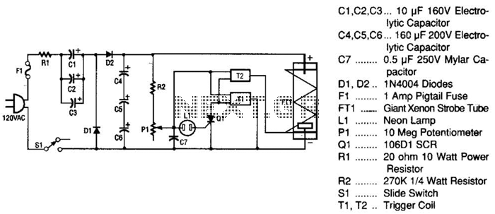
This strobe light operates from standard 120-Vac power. Resistor R1 limits the amount of current applied to the voltage doubler stage, which consists of capacitors C1, C2, C3, and diodes D1, D2, along with capacitors C4, C5, and C6....
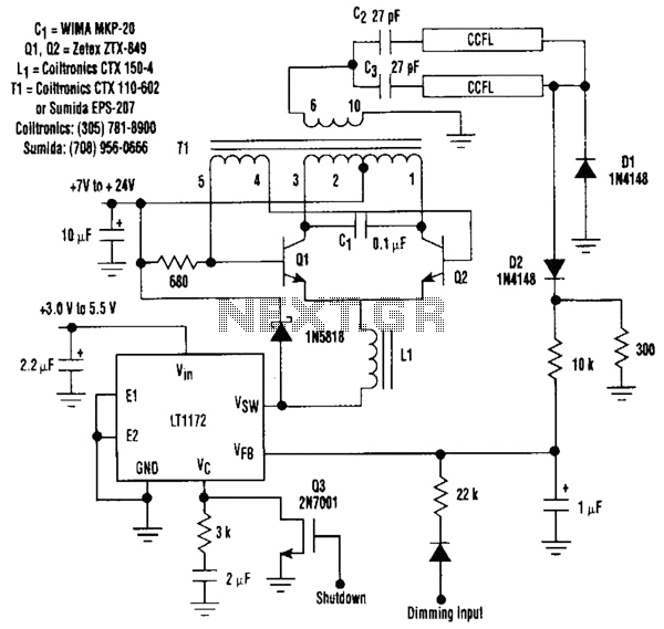
This circuit is a 92%-efficient power supply for cold-cathode fluorescent lamps (CCFLs), which are used to backlight LCDs in portable equipment. The efficiency depends heavily on the component types, particularly C1, Q1, Q2, L1, and T1, whose manufacturers are...