
Relay Toggle with 556 schematic

In operation, the 1uF capacitor will charge to whatever voltage is present at the output on pin 5. When the button is pressed, the capacitor voltage will be applied to the input of the other timer which will reverse the state of both timers and toggle the relay, either on or off.
To follow it more closely, assume the output at pin 5 is +12 volts and the second output at pin 9 is zero volts. The 1uF cap will be charged to 12 volts. When the button is pressed, the cap will apply +12 to the inputs at pin 2 and 6 which will cause the output at pin 9 to go to zero, turning off the relay. When the button is released, the cap will discharge to zero, since the voltage at pin 5 is now zero. When the button is again pressed, the capacitor will apply zero to pins 2 and 6 causing the output at pin 9 to switch positive and engage the relay, and the cycle repeats.
The advantage of this circuit is the large hysteresis range on the inputs. The button can be held closed indefinitely without upsetting the state of the outputs since the input voltage will be 1/2 the supply due to the equal value 100K resistors. The switching points are 1/3 and 2/3 of the supply so that a voltage of 50% has no effect. The circuit will also toggle very fast and needs no switch debouncing. One disadvantage is that it may turn on with the relay either engaged or disengaged. To solve that problem, a resistor in series with one of the reset lines (4 or 10) and a capacitor from the reset line to ground can be used.
The 100 ohm resistor and 100uF capacitor serve to filter noise on the supply line if the circuit is used in an automotive application. They may not be necessary. The circuit may work well without those parts.
This toggle circuit utilizes two 555 timer integrated circuits configured as inverters to achieve a bistable operation. The first 555 timer's threshold and trigger inputs (pins 2 and 6) are set to receive the input signal, while its output (pin 5) reflects the inverted state of these inputs. The second 555 timer similarly operates with its inputs (pins 8 and 12) and output (pin 9) reflecting an inverted state as well. The interconnection between the output of one timer and the input of the other via a 100K resistor ensures that the timers operate in opposite states, creating a toggle effect.
The inclusion of a 1uF capacitor is critical for the timing and toggling mechanism. This capacitor charges to the voltage level present at pin 5 of the first timer. When the button is pressed, this charged capacitor effectively applies a voltage to the inputs of the second timer, which in turn toggles its output state and consequently the state of the relay connected to it. The charging and discharging cycles of the capacitor are what facilitate the toggling action of the relay, allowing for a clear on/off state based on the button press.
The circuit's design benefits from a significant hysteresis range, allowing it to remain stable even when the button is held down continuously. This is achieved through the use of equal value resistors that create a voltage divider effect, ensuring that the input voltage remains at half the supply voltage during steady states. The switching thresholds set at 1/3 and 2/3 of the supply voltage provide a buffer that prevents inadvertent toggling when the input voltage hovers around the midpoint.
In automotive applications, the addition of a 100 ohm resistor and a 100uF capacitor can enhance the stability of the circuit by filtering out potential noise from the power supply. However, these components are not strictly necessary for the circuit's operation and may be omitted if the application environment is deemed stable. Overall, this toggle circuit offers a reliable and efficient method for controlling relays with minimal external components required for operation.This toggle circuit operates by using a couple 555 timers wired as inverters. Pins 2 and 6 are the threshold and trigger inputs to the first timer and pin 5 is the output. The output at pin 5 will always be the inverse of the input at pins 2 and 6. Likewise, the output at pin 9 of the second timer will always be the inverse of the input at pins 8 and 12. A 100K resistor connects the output of one inverter to the input of the other so the state of one will be the opposite of the other.
In operation, the 1uF capacitor will charge to whatever voltage is present at the output on pin 5. When the button is pressed, the capacitor voltage will be applied to the input of the other timer which will reverse the state of both timers and toggle the relay, either on or off. To follow it more closely, assume the output at pin 5 is +12 volts and the second output at pin 9 is zero volts.
The 1uF cap will be charged to 12 volts. When the button is pressed, the cap will apply +12 to the inputs at pin 2 and 6 which will cause the output at pin 9 to go to zero, turning off the relay. When the button is released, the cap will discharge to zero, since the voltage at pin 5 is now zero. When the button is again pressed, the capacitor will apply zero to pins 2 and 6 causing the output at pin 9 to switch positive and engage the relay, and the cycle repeats.
The advantage of this circuit is the large hystersis range on the inputs. The button can be held closed indefinetly without upsetting the state of the outputs since the input voltage will be 1/2 the supply due to the equal value 100K resistors. The switching points are 1/3 and 2/3 of the supply so that a voltage of 50% has no effect. The circuit will also toggle very fast and needs no switch debouncing. One disadvantage is that it may turn on with the relay either engaged or disengaged. To solve that problem, you could use a resistor in series with one of the reset lines (4 or 10) and add a capacitor from the reset line to ground.
The 100 ohm resistor and 100uF capacitor serve to filter noise on the supply line if the circuit is used in a automotive application. They may not be necessary. The circuit may work well without those parts. 🔗 External reference
Related Circuits
Many Video Operated Relay (VOR) circuits have been published in recent years for use in connection with ATV repeater controllers or automatic videotape logging systems. Unfortunately, many of these circuits fail to properly detect certain video signals depending on...
Many individuals find that they sleep well in natural environments, such as tents or wooden huts. This phenomenon is attributed not only to the healthy surroundings but also to our subconscious ability to perceive the Earth's natural magnetic fields....
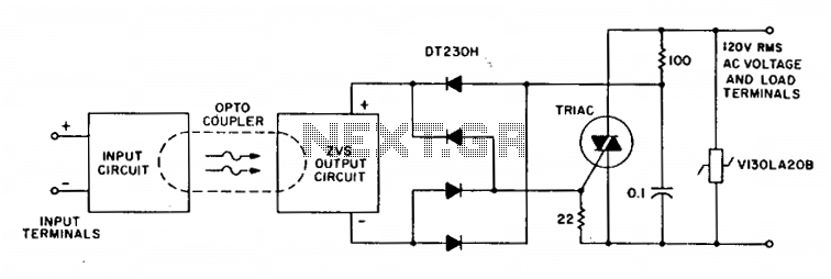
A complete zero-voltage switch solid-state relay consists of an input circuit, an output circuit, and a power thyristor. The circuit features a triac power thyristor with a snubber circuit and GE-MOVRII Vans for transient over-voltage protection. A 22-ohm resistor...
While many power supplies can be set to limit their output current to a defined level to protect the circuit they are powering, no such protection is available. To enhance the safety and reliability of electronic circuits, it is crucial...
This circuit was adapted from the Toggle Switch Debounced Pushbutton by John Lundgren. It is useful where the load needs to be switched on from one location and switched off from another. Any number of momentary (N/O) switches or...
Dunlop Cry Baby Wah Wah Schematic. It is challenging to replicate the Cry Baby sound due to its unique characteristics. The Dunlop Cry Baby Wah Wah pedal is renowned for its distinctive tonal qualities and is a staple in many...