
DC Voltmeters

A direct-coupled amplifier DC voltmeter is an essential instrument for measuring low-level voltages, particularly in applications requiring high sensitivity and precision. The use of cascaded transistors enhances the gain while maintaining low power consumption, which is critical for battery-powered devices. The inclusion of an attenuator allows for flexibility in measuring various voltage ranges without compromising accuracy.
In the FET-based design, the high input impedance ensures minimal loading on the source circuit, which is particularly important when measuring sensitive signals. The direct coupling of transistors Q2 and Q3 allows for a compact design while ensuring that the output remains linear and proportional to the input voltage, a key requirement for accurate voltage measurement.
Chopper amplifiers represent a significant advancement in DC measurement technology, providing improved stability and accuracy over traditional methods. The conversion of DC signals to AC and back again helps to eliminate drift and noise, resulting in more reliable readings. The use of photodiodes in the chopper circuit showcases the integration of optoelectronic components to enhance performance, particularly in environments where electrical noise is a concern.
Overall, these designs illustrate the evolution of voltmeter technology, emphasizing the balance between sensitivity, accuracy, and practical application in electronic measurement systems.This type of voltmeter is very common because of its low cost. This instrument can be used only to measure voltages of the order of milli-volts owing to limited amplifier gain. The circuit diagram for a direct coupled am plifier dc voltmeter using cascaded transistors is shown in figure.
An attenuator is used in input stage to select voltage range. A transistor is a current controlled device so resistance is inserted in series with the transistor Q1 to select the voltage range. It can be seen from figure that sensitivity of voltmeter is 200 kilo ohms/volt neglecting small resistance offered by transistor Q1.
Other values of range selecting resistors are also so chosen that sensitivity remains the same for all ranges. So current drawn from the circuit is only 5micro Ampere. Two transistors in cascaded connections are used instead of using a single transistor for amplification in order to keep the sensitivity of the circuit high.
Transistors Q1 and Q2 are taken complement to each other and are directly coupled to minimize the number of components in the circuit. They form a direct coupled amplifier. A variable resistance R is put in the circuit for zero adjustment of the PMMC. It controls the bucking current from the supply E to buck out the quiescent current. The draw-back of such a voltmeter is that it has to work under specified ambient temperature to get the required accuracy otherwise excessive drift problem occurs during operation.
Another circuit diagram of a direct coupled amplifier dc voltmeter using FET in input stage is shown in figure. In this voltmeter, voltage to be measured is firstly attenuated with range selector switch to keep the input voltage of amplifier within its level.
FET is used in the input stage of amplifier because of its high input impedance so that is does not load the circuit of which voltage is to be measured and it also keeps the sensitivity of voltmeter very high. As FET is a voltage controlled device so resistance network of attenuator is put in shunt in the circuit.
Transistors Q2 and Q3 form the direct coupled dc amplifier whose output is finally supplied to PMMC meter. When transistors work within their dynamic region, the deflec tion of meter remains proportional to the applied input voltage.
This voltmeter can be used for measurement of voltages of the order of milli-volts because of sufficient gain of ampli fier. Apart from the high input imped ance, this circuit has another advan tage that when in put voltage exceeds its limit, amplifier gets saturated which limits the current passing through the PMMC meter.
So meter does not burn out. Chopper type dc amplifier is used in highly sensitive dc electronic volt meters. Its block diagram is shown in figure. Firstly dc input voltage is converted into ac voltage by chopper modulator and then it is supplied to an ac amplifier, i Output of am plifier is then demodulated toa dc voltage proportional to the original input voltage. Modulator chopper and demodulator chopper act in anti-synchronism. Chopper system may be either mechanical or electronic. Circuit diagram of an electronic chopper employing photo diodes is shown in figure. Photo diodes change its resistance under different illumination conditions, this property f photo diode is used in chopper amplifier.
Its resistance changes from the order of few mega-ohms to few hundred ohms when it is illuminated by a light source in the dark place. Two neon lamps are used in this circuit, these are supplied by an oscillator for alter nate half cycles.
Two photo diodes are used in input stage which acts as half-wave modu lators because of its alternate switching action by the neon lamps at the frequency of oscillator. Output of chopper modulator is a square wave voltage (proportional to the input signal) which is supplied to the ac amplifier through a capacitor.
Amplified output is again passed through a capacitor and then fed 🔗 External reference
Related Circuits
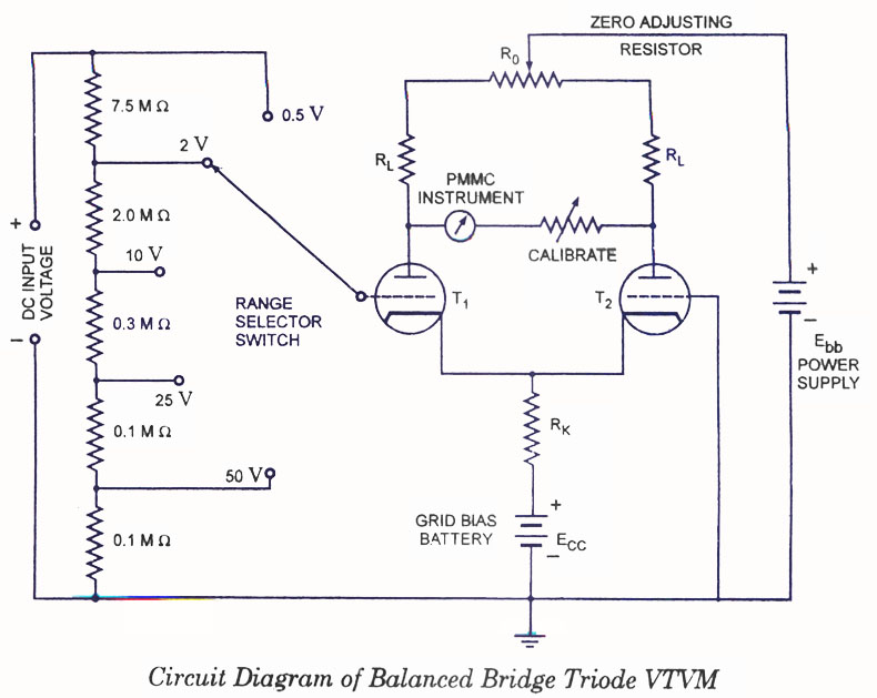
Voltmeters can be utilized for measuring both direct current (DC) and alternating current (AC) voltages and are widely used. These voltmeters are available in two types: vacuum tube and transistorized. In the vacuum tube version, two identical triodes, T1...
Vacuum-tube or electronic voltmeters utilize the unique characteristics of electron tubes and are available in various types. They can measure direct, RMS, average, or peak voltages. Among the many types, the simplest and most commonly used for measuring RMS...
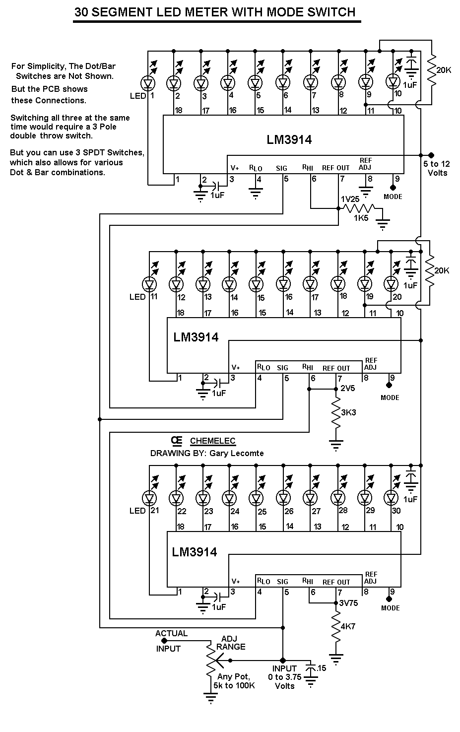
The circuit can be easily configured for full-scale voltages of either 20 or 200 volts by utilizing a suitable potentiometer on the input. It is critical not to exceed 30 volts at pin 5 of the LM3914. A 20...
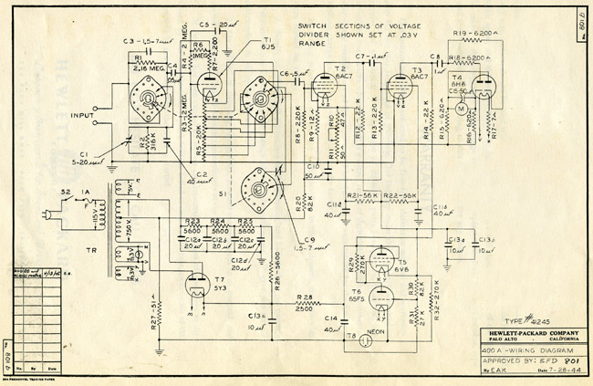
The HP Model 400A Vacuum Tube Voltmeter is highly versatile due to its extensive frequency and voltage ranges. It can directly measure AC voltages as low as 0.005 volts and as high as 300 volts across a frequency range...