
Balanced Bridge Voltmeters

In the balanced bridge transistorized voltmeter (TVM), two identical transistors, Q1 and Q2, are used. When a positive input DC voltage is applied to the base of transistor Q1, the emitter current of this transistor increases, causing a voltage drop across resistor RL, which reduces the collector potential of transistor Q1. The increase in emitter current also raises the voltage drop across resistor RE, leading to a decrease in the emitter current of transistor Q2. This results in an increase in the collector potential of transistor Q2, and a current proportional to the applied input voltage begins to flow through the ammeter connected between the collectors of transistors Q1 and Q2.
A significant advantage of the VTM is that if both transistors Q1 and Q2 are identical, any changes in ambient temperature will affect the parameters of both transistors equally, ensuring that the collector current remains stable under varying temperature conditions. Additionally, changes in ambient temperature will equally affect the saturation current of both transistors, thus keeping the meter reading unaffected. Resistor RE also provides negative feedback for transistors Q1 and Q2; any increase in ambient temperature raises the emitter current, which is limited by the increased voltage drop across resistor RE, typically of high resistance. This mechanism ensures that the calibration accuracy of the TVM is maintained over a broad temperature range. Another advantage is that fluctuations in the power supply, VCC and VEE, do not impact performance since they alter the biasing of both transistors equally. However, a notable disadvantage of the balanced bridge TVM is its lower input impedance compared to other designs.Such voltmeters can be used for measurement of both dc and ac voltages and are very popular. These voltmeters are available in both versions, vacuum tube type and transistorized type and are described below: In this instrument two identical triodes T1 and T2 are used. Plate voltage is applied to both of the triodes through two, identical resistors RL and a variable resistance RQ. Resistance R0 is so adjusted that plate voltages of both of the triodes become equal when there is no voltage applied on the grid of triode T1. So, in this condition, meter connec ted between the plates of the two triodes reads zero. The bias battery ECC biases the cathodes of both of the triodes positive and so the bias of the grid of both of the triodes becomes negative with respect to their respective cathodes.
When a positive dc voltage is applied to the grid of triode T1, potential of grid with respect to cathode increases and so the plate current increases. Due to increase in plate current of triode T1 the voltage drop across the resistor RL connected in series with triode T1 increases and, therefore, plate voltage of triode T1 falls.
The increased current also flows through the resistor Rk which is common to both of the tubes T1 and T2. An increase in current through resistor Rk causes increase in voltage drop across it and, therefore, cathode of triode T2 becomes more positive.
It results in increase of -negative grid bias of tube T2 and therefore, plate current of triode T2 is reduced. With this voltage drop across resistor RL connected with plate of triode T2 falls and, therefore, plate voltage of triode T2 increases.
Thus with the application of dc voltage on the grid of triode T1 voltages of the two triode plates do not remain same and a current flows through the PMMC meter, which is proportional to the applied dc voltage. So PMMC meter can be directly calibrated to read the applied input dc voltage. Range of this instrument can be extended by using a range selector switch and a potential divider network.
For measuring ac voltage with this voltmeter, it is first rectified and then applied to this voltmeter. A resistance is connected in series with the meter for the purpose of setting the full scale reading of the meter accurately.
In balanced bridge TVM two identical transistors Q1 and Q2 are used. When the positive input dc voltage is applied to the base of transistor Q1, emitter current of this transistor increases which causes the increase in voltage drop across resistor RL and therefore, reduces the potential of collector of transistor Q1 With the increase in emitter current, voltage drop across resistance RE increases and so the emitter current of transistor Q2 is reduced. This increases the potential of the collector of transistor Q2 and a current proportional to the applied input voltage starts flowing in the ammeter connected between collectors of transistors Q1 and Q2.
Main advantage of VTM is that if both transistors Q1 and Q2 are similar then with the change in ambient temperature, p values of both the transistors will change equally so there will be no effect on collector current in changed ambient temperature condition. Also with the change in ambient temperature, saturation current of both the transistors will change equally and therefore the meter reading will remain unaffected.
Resistor RE also provides negative feedback for transistors Q1 and Q2 as any increase in ambient temperature also increases the emitter current which in turn is limited by the increase in the voltage drop across resistor RE which is normally of high magnitude. Thus accuracy of calibration of TVM is maintained over a wide range of temperature. Another advantage of TVM is that any fluctuation in power supply VCC and VEE does not affect its performance as it changes the biasing of both the transistors equally.
Main disadvantage of balanced bridge TVM is that it offers less input impedancec 🔗 External reference
Related Circuits
H-Bridge This circuit drives small DC motors up to about 100 watts or 5 amps or 40 volts, whichever comes first. Using bigger parts could make it more powerful. Using a real H-bridge IC makes sense for this size of...
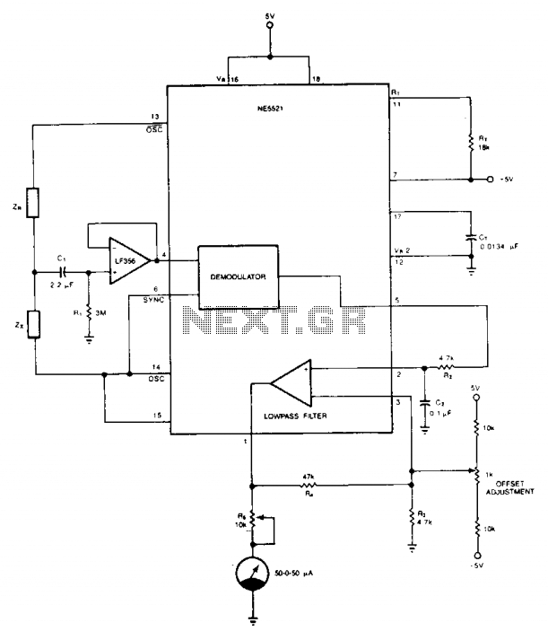
The circuit offers a straightforward and economical approach to matching resistors and capacitors. Impedances ZR and Zx create a half-bridge configuration, while OSC and OSC excite the bridge in a differential manner. An external op-amp, specifically a FET input...
Schematic, breadboard photo, parts list, and results of several transistor variations on the classic bipolar H-bridge motor driver circuit. The classic bipolar H-bridge motor driver circuit is a widely used configuration that allows for the control of DC motors in...
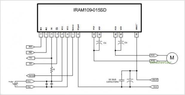
Current during under-voltage lockout (UVLO). When VCC exceeds the UVLO+ threshold, the IR2156 begins to oscillate, and the Charge Pump circuit (CCP, DCP1, and DCP2) supplies the current to VCC. The IR2156 is a versatile integrated circuit designed for driving...
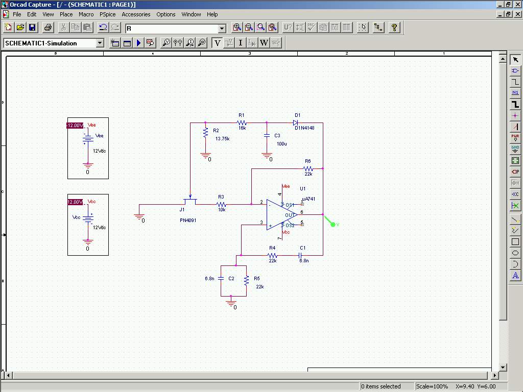
In this experiment, an oscillator is constructed using an operational amplifier along with several passive components. This specific configuration is known as a Wien Bridge oscillator. The frequency of the oscillator is determined by the resistors R4, R5 and...
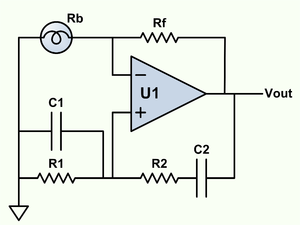
Wien bridge oscillator. A phase-shift feedback oscillator that uses a Wien bridge as the basis for its operation. The Wien bridge oscillator is a type of electronic oscillator that generates sine waves. It operates based on the principle of phase...