
20 & 30 Segment LED Voltmeters

The circuit utilizes the LM3914 LED bar graph/LED dot display driver, which is designed to drive a series of LEDs based on an input voltage. The configuration allows for a flexible full-scale voltage setting, adjustable via a potentiometer. This feature is particularly useful in applications where varying voltage levels need to be monitored or displayed. The input voltage should be carefully managed to prevent exceeding the maximum ratings specified for the LM3914, particularly at pin 5, where a voltage limit of 30 volts is enforced to ensure the integrity of the device.
A critical component of this design is the 20 kΩ resistor connected across the LED output. This resistor serves to balance the output, ensuring that the #10 LED does not unintentionally light up when higher-numbered LEDs are activated in Dot Mode. The placement of this resistor on the copper side of the PCB reflects practical design considerations, primarily dictated by space limitations on the board.
The power supply requirements for this circuit are also essential. The 20 LED version is optimized to operate within a voltage range of 5 to 12 volts, consuming around 10 mA for each LED. Care must be taken to avoid exceeding the 12-volt threshold in Bar Mode to prevent overheating, which can lead to failure of the LM3914. However, the circuit can accommodate a higher voltage in Dot Mode, allowing for operation up to 20 volts safely.
The newly designed version with three LM3914 chips enhances the functionality, with a minimum operating voltage of 3.75 volts for full-scale operation. This design is particularly advantageous for applications requiring lower voltage operation, while still providing a robust output of around 8 mA per LED. This allows the device to handle voltages up to 15 volts in Bar Mode without risking damage to the LM3914, thereby broadening its applicability in various electronic projects and displays.So you could easily set it for 20 or even 200 Volts Full Scale, Using a Suitable Potentiometer on the Input. DO NOT EXCEED 30 VOLTS to PIN 5 of the LM3914`s. The 20 K resistor Shown across the LED is required to null out the #10 LED, when higer LED`s are lit up in Dot Mode.
Leaving this resistor off will cause #10 (Also #20 on the 30 LED one) to l ight Faintly when LED`s above #10 are lit. This 20 K resistor is soldered to the Copper Side, due to space limitations! I designed The 20 LED unit to operate from any Voltage Supply beween 5 to 12 volts MAXIMUM. It runs with about 10 mA per LED and Exceeding 12 Volts Supply Voltage in Bar Mode WILL cause Overheating of the LM3914. In Dot Mode you can Safely operate this circuit up to a 20 Volt supply. This NEW, Three LM3914 Version (Shown Below) has a Minimum 3. 75 Volts for full Scale. It is Programmed for around 8 mA per LED, so it can operate from Voltages Up to 15 Volts in BAR Mode, without damaging the LM3914`s.
🔗 External reference
Related Circuits
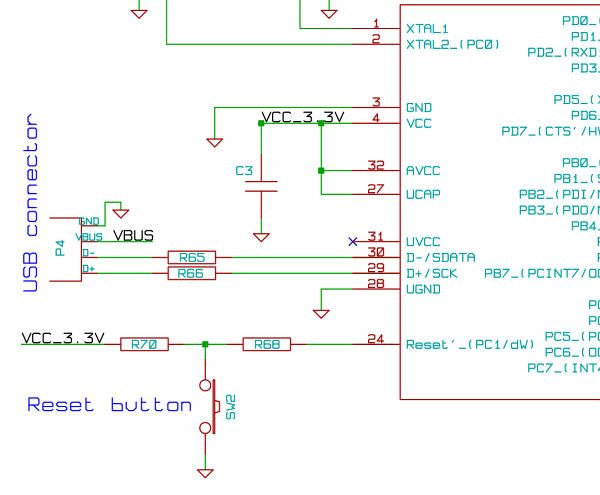
The initial step often taken when learning about any microcontroller or embedded system is to make an LED blink. The circuit presented below illustrates the setup for interfacing an LED. Note: Due to the large dimensions of the circuit...
Common Light Emitting Diodes (LEDs) require a direct current (DC) forward bias of 10 to 20 mA for optimal performance. The maximum allowable DC current typically ranges from 30 to 50 mA. The emitted light color, or wavelength, from...
The microcontroller unit (MCU) will read images from the DataFlash memory via the SPI bus based on the known velocity. It will then send these images to the LED drivers using the SPI bus, controlling the on and off...
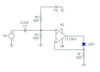
After constructing a Pulse Width Modulator for high-power LEDs, another LED modulator was developed for an optical transceiver. This project utilized a different approach, focusing solely on linear techniques for audio modulation. Similar to the PWM circuit, this circuit...
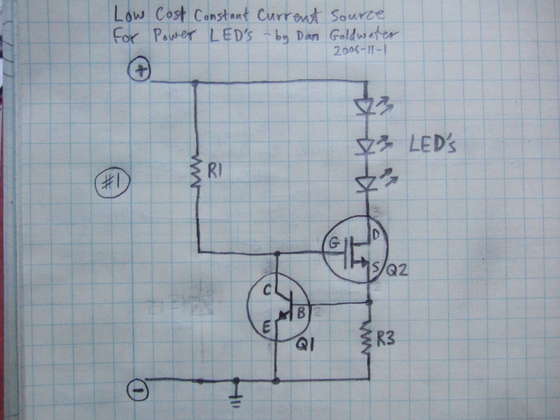
Here is a simple and cost-effective Power LED driver circuit. This power LED driver circuit is designed to efficiently drive high-power LEDs with a stable output. The circuit typically consists of a few key components: a power supply, a current...
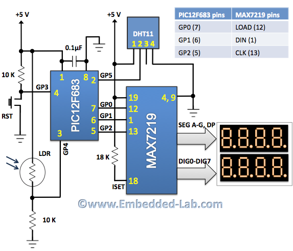
An automatic brightness adjustment is a closed-loop system that has the capability to assess ambient light and adjust the brightness of the display accordingly. The automatic brightness adjustment circuit operates by utilizing a light sensor, typically a photoresistor (LDR) or...