
Dean Forest Railway Telecoms

The circuit operates through a series of relays and keys that manage the communication line and alert the operator to various states of operation. The line keys serve as the primary control mechanism, allowing the operator to select between waiting for a call, connecting to the common equipment, or testing the line. The PHA relay circuit plays a crucial role in ensuring that only one communication path is active at any time, preventing cross-talk or interference between signals. The interaction among the relays ensures that the system can handle multiple states, including normal operation, fault detection, and alert signaling.
The design incorporates a fail-safe mechanism, where the lamp remains lit if a call is not answered within the specified timeout, providing a visual indicator of potential issues. The use of timing relays allows for precise control over the signaling process, ensuring that alerts are both timely and informative. The modification of the ringing circuit to accommodate direct current during silent periods demonstrates a thoughtful approach to maintaining system integrity while ensuring effective communication.
Overall, this circuit exemplifies a robust design suitable for railway signaling applications, where reliability and clarity of communication are paramount. The integration of various components, such as the K relay, PHA relay, and timing relays, creates a comprehensive system capable of managing complex signaling requirements effectively.Each line key has three positions. Centralised it connects the line circuit to line to await a call. Downwards (KK) it operates a K relay which switches the line through to the common equipment. Upwards (KL) the line is connected to the line tester. The tester normally sends an earth on both legs to line, therefore any line with the key up is norm ally earthed both legs and can be left in that state if it should go faulty. The lamp is normally out. If the SPT calls then it is flashed at a rapid rate. When the call is answered the lamp goes out. Should the call not be answered after a timeout period (2min 30sec) the lamp remains permanently lit. If the signaller calls the SPT, he operates the line key and then momentarily operates a ringing key.
This causes ringing to be sent to line and the line lamp flashes slowly in synchronism with the ringing cadence. The common equipment has a standard transmission bridge which is connected between any SPT and the signalman`s telephone circuit by the operation of the SPT speak key and the operator`s key.
The PHA relay circuit is of interest. It was derived from the IRSE text book on Railway Signalling and consists of a relay connected across a bridge circuit. If no speak key is thrown, then no current flows and the PHA relay remains released. If one speak key is thrown, then 450 ohm earths are connected to each side of the PHA relay which is balanced and remains released.
If more than one key is thrown then 450 ohms is connected to the right hand side of the PHA relay and 225 ohms or less on the left hand side. This unbalances the circuit and current flows through PHA to operate it. PHA1 disconnects the earth from the SC wire thus preventing any K relay operating in the line circuits.
PHA2 also operates the main warning light and the buzzer to tell the operator that he is misoperating the equipment. A calling L relay in a line circuit, or the PHA relay operating lights the main warning lamp and starts the buzzer.
At the same time relay SB starts its slow to operate feature. It takes a second or two to operate. The long/short buzzer key can select whether to use the period after the SB operation to ring the buzzer continuously or the short time before the SB operation to give just a quick call on the buzzer. In either case the main lamp lights continuously. If the sound of the buzzer is annoying, it can be silenced temporarily by operating the buzzer cut off key momentarily.
This operates relay BCO which holds to the calling condition. It disconnects the buzzer but leaves the calling condition on to light the main lamp. The ring trip circuit is of interest as it had to be modified from the standard circuit element. The ringing converter has a 2150 ohms output winding on the coil. Whilst this would ring a bell satisfactorily it would not permit sufficient direct current to flow to allow the F relay in the circuit to trip the ring. In the end it was decided to modify the ringing circuit so that DC only flows during the "silent period".
Relay RT was added which operates each time ringing occurs. During the silent period RT is released and connects a 270 ohm battery out to line in place of the 2150 ohm earth from the converter. During this period sufficient current flows around a looped line to operate the F relay to trip the ring.
Ring trip though cannot occur during the ringing phase. The timing relays are started by an earth on the STA lead. This operates relay ST which in turn causes relays FE and FR to interact and allow relay FE to provide a "flicker earth" pulse. This flicker earth at FE5 flashes any calling lamp rapidly. From here the relay set times out to around 2 mins 30secs. Relays RA and RB divide the FE1 pulses by two, RC and RD reduce the pulse frequency by a further factor of two, as do relays RE and RF.
Over all the pulse frequency is divided by eight. Various timings can be picked off the relay dividers. In partic 🔗 External reference
Related Circuits
Children today appear to possess nearly all the items available in toy stores. Therefore, if there is a son or grandson with a collection of toy cars, here is a suggestion for an addition to that collection. For enhancing a...
The mine railway connects the national railways and intermediate links of the mining area, serving as an important component of the railway transport network. Statistics indicate that the Chinese mine railway extends over 20,000 kilometers, with numerous road junctions...

Digital Command Control (DCC) provides significant advantages over traditional DC analog control systems, primarily due to its simplified wiring. DCC enables the individual control of multiple locomotives on the layout without requiring electrical isolation of track sections. The main...
The protected section of track can be of any desired length and does not need to be equal on both sides of the crossing. The circuit operates bidirectionally and can be linked with other grade crossing circuits to provide...
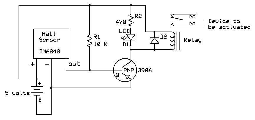
A sensor used in garden railway applications, Hall Effect sensors are the electronic equivalent of a reed switch. They can be thought of as a combination of a reed switch and a transistor. These sensors are commonly employed to...
Dedicated model rail enthusiasts using sophisticated train and point controllers often encounter the issue that as their layouts expand and become more complex, the transformer supplying power to the points does not provide sufficient current to switch multiple points...