
Railway Points Sequencer

The circuit design effectively addresses the challenges faced by model rail enthusiasts with complex layouts. By implementing a sequencer, it ensures that only one point actuator is powered at any given time, thus preventing overheating and potential damage to the coils. The 555 timer operates in astable mode, generating a continuous square wave signal that drives the 4017 Johnson counter. This counter sequentially activates the triacs, which are responsible for controlling the current flow to each point actuator.
The adjustable resistor P1 allows users to fine-tune the frequency of the 555 timer, accommodating different types of point mechanisms that may have varying switching times. The typical range of 1 to 1.5 seconds provides a balance between operational efficiency and safety, ensuring that the actuators have adequate time to complete their movement before another is activated.
The inclusion of an LED indicator connected to the 4017’s eleventh output serves a dual purpose: it provides a visual cue for the operator regarding the sequencer's activity and helps in troubleshooting by indicating which point actuator is currently active. Additionally, the audible feedback from any jammed points aids in maintenance, allowing for prompt resolution of mechanical issues.
Overall, the circuit is powered by a robust 15 V AC supply, with the B80C1500 bridge rectifier converting this to a stable 12 V DC output, ensuring reliable operation of the sequencer and connected components. The low current consumption of just a few milliamps further enhances the efficiency of the design, making it suitable for various model railway applications.Dedicated model rail enthusiasts using sophisticated train and points controllers often have the problem that as their layouts get bigger and more complex, the transformer supplying power to the points does not have enough current to switch several points at the same time. The actuators in the points are designed for ac operation so it doesn`t hel p by rectifying the supply and adding reservoir capacitors, the coils can overheat and burn out if they get jammed during their travel (ac operation actually helps to overcome friction in the mechanism). The circuit shown here solves this problem by using a sequencer to ensure than only one points actuator can be active at any point in time.
During operation the controller will switch all the points on one line at the same time as usual, but the other connection to each coil is connected to the sequencer unit. This circuit will only allow current to‚ow through one coil at a time. The sequencer circuit consists of a 555 timer congured as an astable multivibrator clocking a 4017 Johnson counter where the ten outputs are used to switch ten triacs in sequence, enough for ten sets of points.
P1 alters the oscillator frequency of the 555 timer and can be adjusted so that each time interval of the sequencer is long enough to allow the points to switch. The switching time varies depending on the type of points but is typically between 1 s and 1. 5 s. Any points that jam during switching give out a characteristic humming noise in time to the switching frequency so it makes them easier tond.
The eleventh output of the 4017 can be connected to an LED (together with a series resistor). This will flash to give a visual indication of the sequencers operation. Power for the circuit is provided by 15 V ac from the points transformer. The B80C1500 bridge rectifier (80 Vpiv, 1. 5 A) and regulator IC1 produce a stabilised 12 V for the circuit. Current consumption is only a few milliamps. 🔗 External reference
Related Circuits
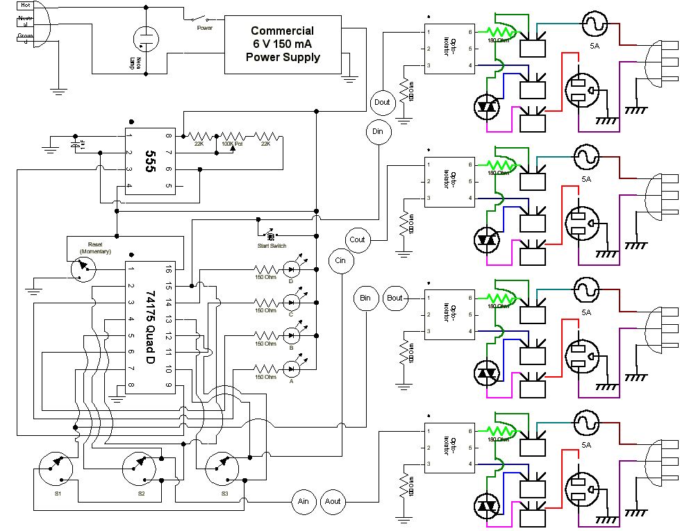
This is a sequencer circuit. Power to the logic portion of the circuit is provided by a standard commercial "wall-wart" power adapter supplying 6 VDC. The 555 timer IC generates the pulse train that drives the chase, with timing...
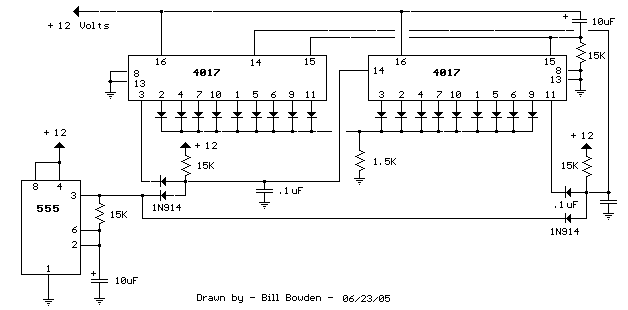
When power is applied, the 15K resistor and 10µF capacitor at pin 15 will reset the counters to a zero count, with pin 3 at +12V and all other outputs at zero. The two diodes (1N914) and a 15Ω...
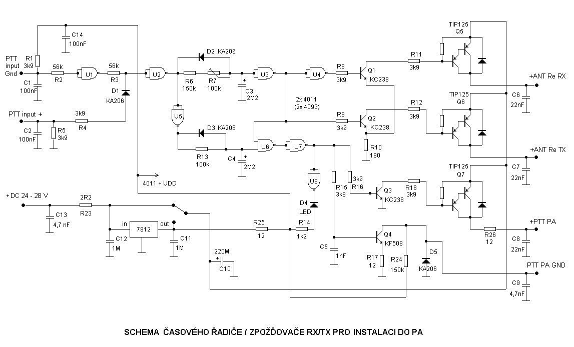
The next task involves replacing the LNA transistor; however, issues have already recurred in the subsequent context. This problem typically arises from an inappropriate timing sequence when switching between receiving and transmitting modes. Due to various delays, such as...
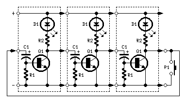
The purpose of this circuit is to create a ring in which LEDs or lamps illuminate sequentially. Its main feature is high versatility; it can accommodate any number of LEDs or lamps, as each illuminating device has its own...
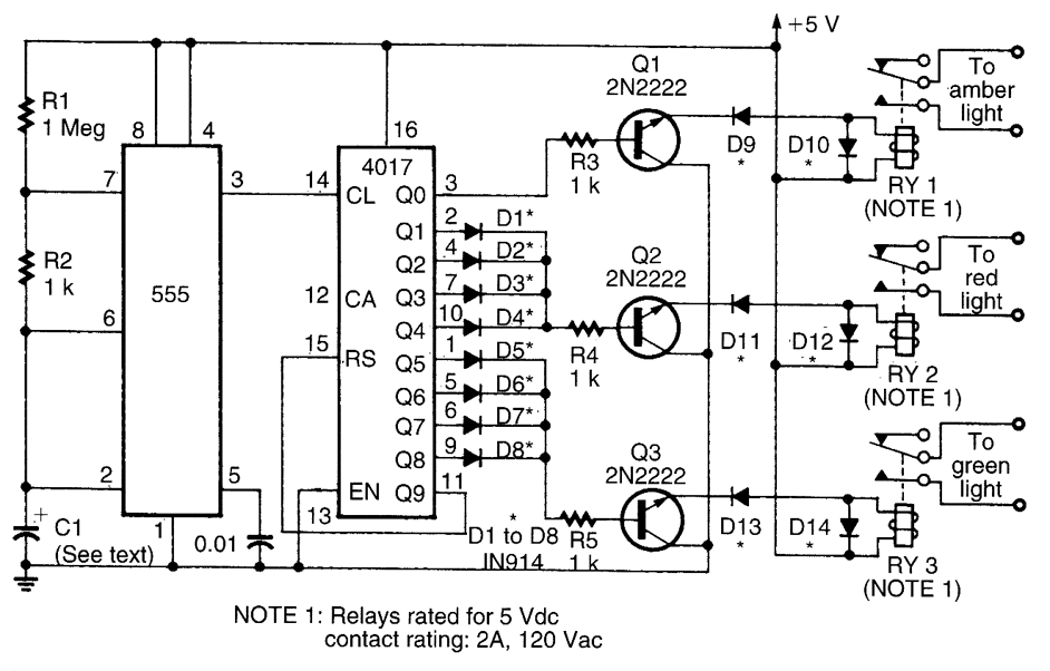
This circuit utilizes a 555 timer to control a 4017 decade counter. The outputs from the counter are used to drive transistor relay drivers. The duration for which the lights remain "on" can be adjusted by modifying the connections...
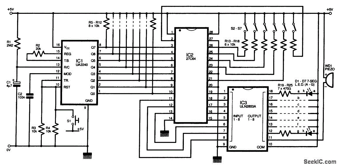
The circuit diagram of this programmable sequencer can be utilized for various timing applications. An audible tone is generated before the start of each interval, while a seven-segment LED display indicates the current interval number. A buzzer sounds again...