
Garden Railway Sensors

In a computer's floppy disk drive, the rotational speed of the platter is detected by a Hall Effect sensor positioned at the 7:00 location, with the attached small magnet visible just to its right. By measuring the duration of each rotation, the speed can be calculated and adjusted by the drive's electronics. In garden railway applications, Hall Effect sensors can replace reed switches in most instances. Their primary benefits include compact size and the absence of mechanical components that may fail. However, they require a three-wire connection and may necessitate additional circuitry for integration with other devices. Furthermore, most Hall Effect sensors, including the one discussed here, are responsive to only one pole of a magnet, requiring careful magnet placement for effective operation. The sensor under consideration is the Panasonic DN6848-ND, available from Digi-Key for slightly over $1.00 in small quantities. The open collector output of this sensor allows for straightforward connections to other devices.
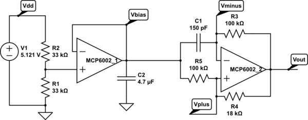
The accompanying schematic provides a means to test the sensor's functionality. While the DN6848 operates within a voltage range of 5 to 16 volts, it is advisable to use the lowest voltage for testing and experimentation. When the south pole of a magnet approaches the front side of the sensor, the voltage displayed on a meter should drop from 5 volts to 0 volts, returning to 5 volts upon magnet removal. Hall Effect sensors can directly trigger sound boards as described in previous articles, requiring only a common ground and a connection from the Hall sensor output to the activation switch. It is recommended to use a current-limiting resistor of approximately 1000 ohms in series with the Hall output to prevent potential issues. The safest connection method involves using a relay. The schematic illustrates the necessary components, which include a 5-volt relay, such as the reed relays available from Radio Shack (#275-232). A PNP transistor (2N3906, 2N2222, or equivalent) is used to activate the relay when the output from the DN6848 drops to 0 volts. An LED (D1) serves as an indicator for relay activation, while a diode (D2, 1N4001 or equivalent) across the relay coil safeguards the circuit from voltage spikes generated during relay deactivation. To activate the sound board, connect the terminals responsible for sound initiation to the normally open (NO) and common terminals of the relay.
In summary, Hall Effect sensors offer a reliable and efficient alternative to traditional reed switches, particularly in applications requiring compactness and durability. Proper circuit design and component selection ensure effective integration and operation within various electronic systems.A sensor in garden railway applications. Hall Effect sensors are the electronic equivalent of a reed switch. You can think of them as a cross between a reed switch and a transistor. They are frequently used to determine the rotational speed of a spinning device, such as the platter of a hard drive or the drive shaft of an automobile. A small magnet is attached to the spinning object so that it goes past the Hall sensor as it rotates. The sensor sends one pulse to a counting circuit each time the magnet passes. I have also seen computer keyboards that have a magnet under each key that comes close to a Hall sensor on each key press. A nice system as there are no mechanical switches to wear out! This photo shows the bottom side of a computer`s floppy disk drive. The rotational speed of the platter is measured by the small Hall Effect sensor that you can see at the 7:00 position.
Just to its right you can see the small magnet that is attached to the platter. By measuring the time needed for each rotation the speed can be measured and adjusted by the electronics on the drive. In garden railway applications Hall Effect sensors can be used in most places where a reed switch would be employed.
Their main advantage is their small size and lack of mechanical parts that are prone to failure. On the down side you must run three wire cable to them and it can take a bit more circuitry to connect them to another device. In addition most Hall Effect sensors, such as the one used in this article, respond to only one of a magnet`s poles.
This forces us to be a bit more careful when mounting magnets that will stimulate a Hall Effect sensor. The device I am working with here is Panasonic part number DN6848-ND. It is available from Digi-Key ( ) for a little more than $1. 00 each in small quantities. The open collector output of this sensor provides for a fairly straightforward connection to other devices.
The schematic below will allow you to test the operation of the sensor. Even though the DN6848 will operate from voltages from 5 to 16 volts try to stick with the lowest operating voltage when testing and experimenting. When the south pole of a magnet is brought near the front (label) side of the sensor the voltage displayed on the meter should drop from 5 volts to 0 volts.
When the magnet is removed the voltage should return to 5 volts. Hall Effect sensors can be used to directly trigger some of the sound boards that were described in the two parts of Give Your Railway a Voice. All you need to do is to provide a common ground and connect the output from the Hall sensor to the activation switch.
A bit of experimentation may be needed but I got several of them to work using this method. If you do give this a try I would suggest using a current limiting resistor, 1000 ohms or so, in series with the Hall output when connecting to the activation switch. Might prevent some unfortunate results! The safest way to connect a device, however, is with a relay. Examine the schematic below to see what is involved. The relay can be any 5 volt unit such as the reed relays that are sold by Radio Shack (# 275-232). The PNP transistor (2N3906, 2N2222 or equivalent) turns the relay on when the output from the DN6848 drops to 0 volts.
The LED, D1, is just an indicator to show that the relay has been activated. The diode, D2, (1N40001 or equivalent) across the relay`s coil protects the circuit from a spike that is generated when the relay is turned off. To activate the sound board just connect the wires from the terminals that start the sound to the NO and common terminals of the relay.
You will note that this circuit will only activate the relay 🔗 External reference
Related Circuits

The LMP91200 is a configurable sensor analog front-end (AFE) designed for managing low-power analytical sensing applications, specifically for 2-electrode sensors. This device offers all the necessary functionality to detect changes based on a delta voltage from the sensor. It...
A touch sensor relaxation oscillator is utilized in the hysteresis lab. In this schematic, the variable capacitor is represented by a person's finger and a touch plate made from aluminum foil and packing tape. Code was developed for the...
It has been some time since there has been substantial progress on the micromouse project. However, recent efforts have focused on the design of the sensor. This work remains theoretical, as additional components are required for testing beyond simulation....
An efficient automatic solar garden lights circuit with minimal components. The advantage is that it operates entirely autonomously, with the solar panel functioning as a light detector. It switches the lamp off at dawn, charges the battery during the...
The ability to perceive colors, shapes, distances, spatial relationships, motion, and connectivity is integral to human experience and cognition. This perceptual framework enables interpretation of sensory information through a complex model of the environment. Robots, however, lack such inherent...
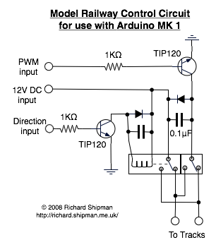
A model railway operates under computer control, utilizing a laptop to send commands via the USB port to an Arduino. The Arduino employs PWM (Pulse Width Modulation) to regulate the speed of the train. There were several challenges encountered,...