
Decatron Clock Project

The decatron is a type of cold cathode counting tube that operates based on the principle of glow discharge. It consists of a central anode surrounded by multiple cathodes and guide electrodes. The cathodes are arranged in a circular pattern, allowing for the selective transfer of the glow discharge from one cathode to another. The unique design of the decatron enables it to function as both a display and a counting device.
In a typical application, the decatron can be connected to a microcontroller or processor, allowing for digital control of the glow discharge. The microcontroller generates the necessary control signals to manipulate the voltages applied to the guide electrodes. By carefully timing these signals, the microcontroller can create the desired visual effect of the digits rolling forward or backward, akin to a slot machine.
The performance of the decatron is influenced by several factors, including the applied voltages, the timing of the control signals, and the physical characteristics of the tube itself. The glow discharge is initiated by applying a high voltage to the anode, which ionizes the gas inside the tube, creating a conductive path. The glow can then be moved between the cathodes by controlling the voltages on the guide electrodes. This method allows for smooth transitions between numbers, enhancing the visual appeal of the display.
The decatron's ability to count is achieved through its unique design, which allows it to maintain the state of the glow discharge across its electrodes. This counting function can be utilized in various applications, including timers, counters, and other digital display systems. The integration of a decatron into a project requires careful consideration of the circuit design, including the necessary power supplies and control logic to ensure reliable operation.
Overall, the decatron represents a fascinating intersection of display technology and counting mechanisms, offering unique visual effects and functional capabilities that can be leveraged in various electronic applications.Instead of simply incrementing the time every new second, it would be great to have a display of forward- and backward-spinning digits, slowly rolling-out to the new time, a little bit like the reels of a slot machine. Having never encountered them, decatrons are completely new to me. How do they work, how to interface them to a processor Instead of working on it for a few months or so and then writing a new web-page on it, I decided to present this page in the form of a web-log. The idea is that this page is expanded every time the project has advanced a bit. Like the E1T "scaling tube" the decatron preceded the nixie tube, perhaps not by invention, but certainly by application.
The most likely reason is that, besides a being a display device, both the Scaling Tube and the Decatron perform the counting function themselves, whereas Nixie tubes require quite a bit of electronics to make them work. They are both small wonders of ingenuity. The Decatron was first announced in a paper in Electronic Engineering of May 1950 entitled: "The Decatron, A New Cold Cathode Counting Tube" by R.
C. Bacon and J. R. Pollard from Ericsson Telephones Research Laboratories, Nottingham, England [4]. The paper discusses the general operation, the performance, and the circuit requirements. The working of the Decatron is best explained in the words of the inventors: A cathode glow on one of a set of inter-connected cathodes, arranged around a central common anode, is caused to transfer from one position to the next by application of controlling voltages to intermediate electrodes or "guides". This arrangement will become clear by considering Figs. 2 and 3. Fig. 2 shows, around the central anode disk A, a number of equi-spaced rods or wires (on a pitch circle of 20mm.
diameter in the case of GC10A). These wires actually comprise thirty electrodes, of which ten are cathodes, ten are guide 1 electrodes, and ten guide 2 electrodes. Nine of the cathodes are connected internally in the sequence shown in part in Fig. 2. The tenth cathode is isolated and brought out separately, as the output or marking cathode. The ten guide 1 electrodes are connected internally, g1, g1a, g1b, etc. , and in the same way the ten guide 2 electrodes marked g2, g2a, etc. , are internally linked. Hence the tube has five outlets, comprising anode, output cathode, cathode ring, guide 1 ring and guide 2 ring.
Referring to Fig. 2, together with the simple circuit arrangement of Fig. 3, let it be assumed that a discharge is taking place between anode A and cathode k2. If a negative pulse of 120 volts is applied to the group of guide 1 electrodes (g1, g1a, etc. ) which were originally at +60 volts with respect to the cathode k2, a transfer of the glow will take place in a clockwise direction to electrode g1a. That is to say the glow discharge will transfer preferentially one position clockwise as opposed to two positions anticlockwise to electrode g1.
If it be arranged that simultaneously with the restoration of guide 1 to +60 volts, a similar pulse is applied to guide 2, the glow will move clockwise to electrode g2a. The function of the two guide systems is thus to render certain the direction of motion of the discharge.
When guide 2 is 🔗 External reference
Related Circuits
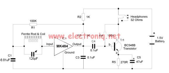
The MK484 AM radio circuit offers a comprehensive solution featuring an RF amplifier, detection, and an automatic gain control (AGC) circuit. It requires only a few external components to achieve high-quality AM tuning. The circuit has an input impedance...
A NIXIE tube was mounted on a wooden cigar box, with the anode connected through a large series resistor to the live wire of a 220V mains supply. Touching one of the cathodes caused the numbers to glow, sparking...

This is a simple automatic light switch circuit designed for bedrooms. After construction, the input terminals of this circuit should be connected in parallel to the intended lighting fixture. The automatic light switch circuit utilizes a light-dependent resistor (LDR) as...
An electronic project to construct an LC meter project kit of exceptional accuracy to measure both inductance and capacitance—an inductance meter and capacitance meter all in one unit. It is readily available as a comparatively inexpensive kit, which is...
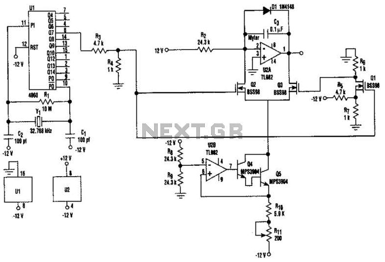
U2-a, U3, and R2 function as an integrator. Q2 and Q3 are alternately switched at 256 cycles. U2-b, Q4, Q5, and R8 through R11 form a constant current generator, with R11 configured to produce a symmetrical triangular waveform. The circuit...

The TEA5551T monolithic integrated radio circuit can be utilized to design an AM radio receiver circuit intended for portable use with headphones. This circuit incorporates all necessary components for a complete AM radio receiver, including a fully integrated AM...