
decoder

The circuit described operates as a versatile controller for model train systems, integrating both power management and signal processing capabilities. The dual drivers facilitate the control of high-current loads, such as turnouts, ensuring that the system can handle the demands of a complex model railway layout. The inclusion of an optocoupler enhances the reliability of the DCC signal transmission, isolating the control signal from the power supply to prevent interference and ensure stable operation.
The 7805 voltage regulator is a crucial component, providing a stable 5V output for the microcontroller, which is essential for maintaining consistent performance across various operational conditions. The design allows for flexibility in power supply choices, accommodating both AC and DC sources, thus broadening the range of compatible transformers and adapters.
The integration of the ULN2803 driver allows for simple interfacing with inductive loads, essential for driving coils in turnouts. The design considerations regarding the free-wheeling diode and potential inductive spikes demonstrate a thorough understanding of the electromagnetic characteristics of the components involved.
The use of the Atmel ATmega8515 microcontroller, with its RC oscillator, provides a cost-effective solution with sufficient timing accuracy for the application. The ability to omit external components simplifies the design and reduces costs, making the circuit accessible for hobbyists and professionals alike.
Overall, this circuit design exemplifies a well-thought-out approach to model train control systems, balancing performance, reliability, and ease of use while addressing potential challenges associated with inductive loads and signal integrity.There is also a version without SMD. This version is called 2. 1, slightly larger (80 * 100 mm) and equipped with dual drivers (to 1A load), but runs with the same software. The input voltage of the external power supply is fed to X2 (15V), type of current(AC/DC) or polarity does not matter, therefore a model train transformer, a power adapter or
the DCC signal can be used. The signal DCC can be also passed along on the board itself without external bridge by closing solder jumpers SJ6 and SJ7. The input voltage is rectified and by means of the usual 7805 series regulator the 5V for the processor are generated.
The idle current is about 20mA, both the T0220 and the smaller T039 can be fitted. Note 1: I`ve noticed that some of Roco turnouts only switch at 15V, in this case due to the voltage drops across the rectifier and output driver the supply voltage need to be increased to 16V AC or 18V DC. Note 2: If only servos or DMX will be controlled, then a lower supply voltage of 7-9V makes life much easier for the 7805.
I use here plug power supplies, which are `cheap` at the next recycling centre. The DCC signal is connected to X1. It is separated from the voltage supply of the decoder via an optocoupler (6N136). The optocoupler ensures a trouble-free operation even in large systems. 6N136 as well as 6N137 or 4N25 can be used. With 6N137, in addition, the Pin 7 (enable input) must be connected to pin 8 (this is not in the layout, because this pin must remain free when 6N136 is used). The 4N25 (or its derivatives) must be mounted as follows: pin 1 of the 4N25 connects to pin 2 of the layout (thus pin 1 of the layout remains unconnected).
The 4N25 is relatively slow; in particular the release time is relatively long. The pull-up (R5) at the output must be scaled down to 1k, otherwise there are only distorted signals after the optocoupler. Here the usual ULN2803 is used with a DIL package so that it can be easily socketed. This driver can deliver 0. 5A continuous current per output; it is internally equipped with a free-wheeling diode for inductive loads.
The outputs are combined in groups of three terminals to allow for an easy installation Turnouts are usually driven by coils and are equipped with a final position turnoff-contact in the drive. The final disconnection causes an induction tension which flows backwards the the driver and is conducted by the integrated free-wheeling diode.
If this switch "flutters" and turns on and off repeatedly quickly in a short time, it can happen that the free-wheeling diode is overloaded before the trip point of the polyfuse. Moreover, the turning-off causes a significant field in this area - therefore turnout wiring may not be long, they should also not be routed parallel to other cables and should be twisted.
The Atmel ATmega8515 is supplied with a RC oscillator that runs at 8 MHz, the crystal and the capacitors can be omitted. The hex file to be loaded must match for this frequency, so if this value is set during compilation (F_CPU) to 8, 000, 000, all timing settings are adjusted automatically.
Note: the timing accuracy is specified by Atmel with 3%, which is sufficient for this application. Although under extremely unfavourable combination of clock deviation, temperature, supply voltage, delays in the optocoupler _and_ a DCC signal on the edge of the allowable timing a malfunction can happen. If you prefer to be hyper precise, you can fit a crystal (and the additional 18pF capacitors). However, a hex file for the selected frequency must also be loaded. Of course, during compilation a value (F_CPU) in accordance with the clock rate must be provided, all the timing settings are adjusted automatically.
Also processor fuse bits must be changed accordingly to "external crystal". 2 slots for servos are provided, the usual pinout GND - +5V - Control is used. The servos are always supplied with +5V and depending on the setup, the contro 🔗 External reference
Related Circuits
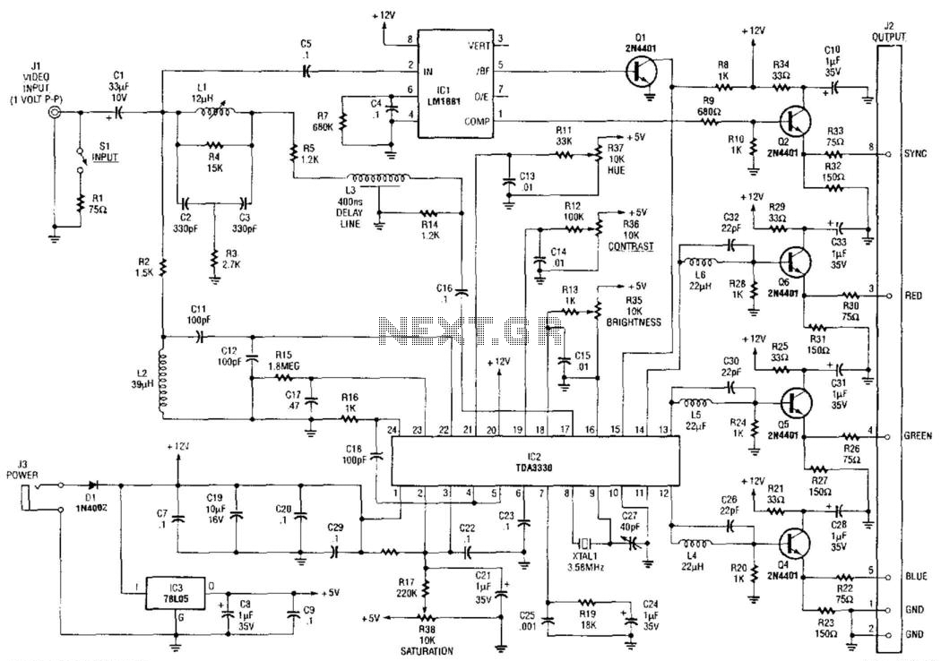
An NTSC/RGB decoder is presented here. Utilizing a TDA3330, a 1-V input video signal is decomposed into its red (R), green (G), and blue (B) components, along with composite sync. U1 serves as an integrated sync separator (LM1881). This...
The phone system used to be operated by a human operator in a telephone exchange room. The caller would pick up the phone and give instructions to the operator to connect their line to the destination on the other...
The Supertex HV440 is utilized for creating a pulse width modulated high voltage ring generator in telecommunication applications. The HV440 can function in both closed-loop and open-loop configurations. A closed-loop design, while more intricate, offers improved load regulation and...
To simplify the driver circuit, a multiplexer circuit can be utilized as a solution. With this multiplexed BCD decoder, only one BCD is required. A multiplexer (MUX) is an essential component in digital circuits, allowing multiple input signals to be...
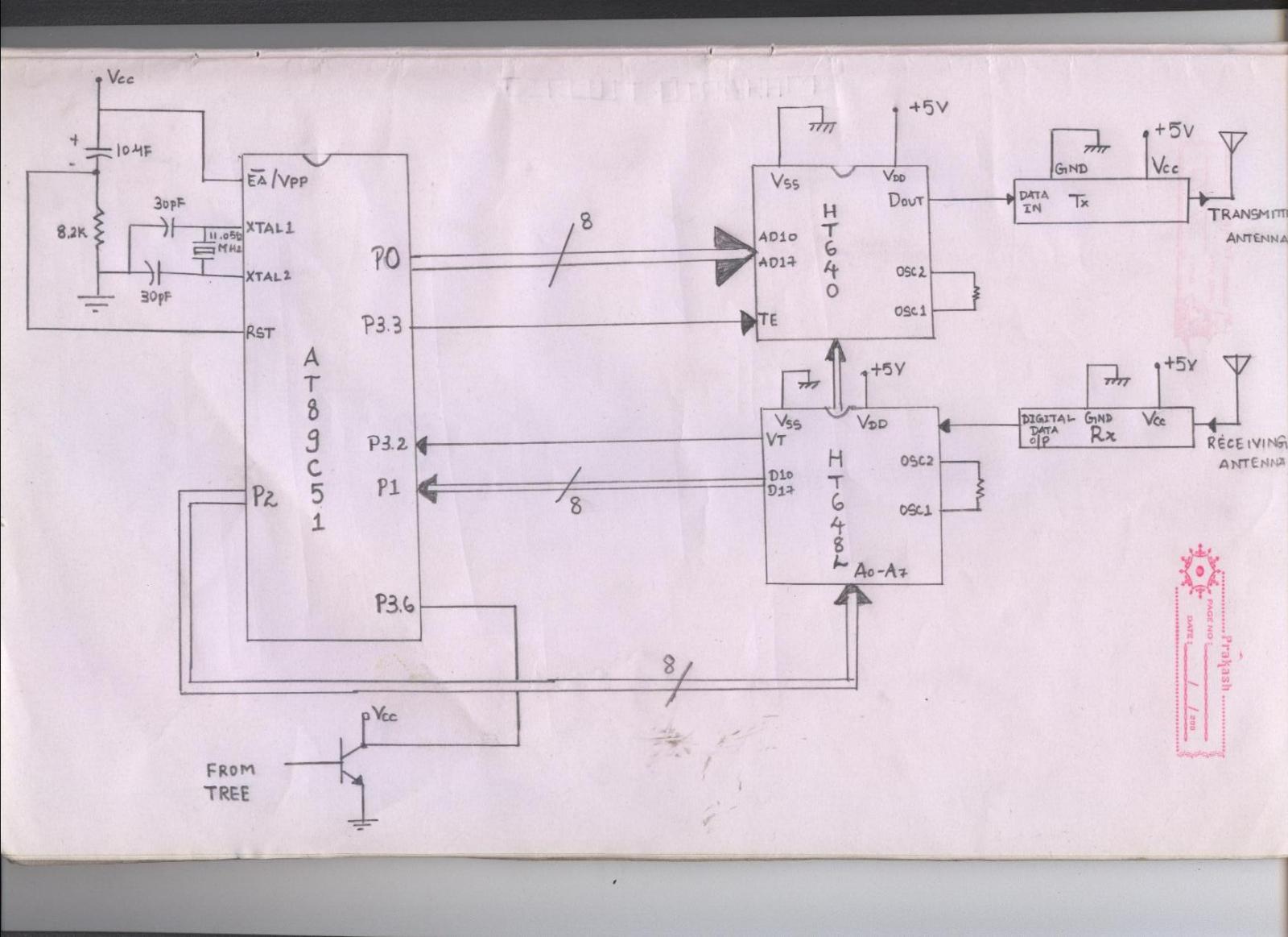
The issue arises when connecting the 8051 microcontroller to the HT640 encoder; the data transmitted is not received by the receiver. However, when the 8051 connections are removed, the transmission functions correctly. This indicates that manual RF communication works...
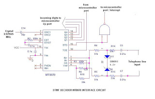
This is a straightforward circuit utilizing the DTMF decoder MT8870 (or CM8870). As illustrated in the circuit, an interrupt will be generated (if the NAND output is connected to the INT of the microcontroller) whenever a call is received...