
microcontroller 8051 rf tx rx encoder decoder

The described issue highlights the need for careful consideration of interfacing between the 8051 microcontroller and the HT640 encoder, as well as between the HT648L decoder and the 8051. The quasi-bi-directional nature of the 8051's ports means that the voltage levels can be affected by the weak pull-ups present on these ports. To resolve the communication problem, it is advisable to ensure that the TE pin of the HT640 is driven correctly. The weak pull-up from the 8051 may not be sufficient to overcome the pull-down at the TE input, leading to indeterminate logic levels that can disrupt communication.
One potential solution is to implement a buffer or a level-shifting circuit that can provide a stronger drive to the TE pin, ensuring that the voltage levels are compatible and reliable. This could involve using a transistor or a dedicated logic level converter to isolate the 8051 from the encoder, allowing for proper signal integrity. Additionally, verifying the connections and ensuring that there are no short circuits or incorrect wiring is essential. It may also be beneficial to consult the datasheets of all components involved to confirm that the electrical characteristics align with the expected operational parameters. By addressing these interfacing challenges, reliable communication between the 8051 microcontroller and the encoder/decoder system can be achieved.The problem is when i connect the 8051 to the encoder the data send is not received at the receiver but as soon as the 8051 connections are removed the transmisison works perfectly. thus manually the RF communication works perfectly i. e the 8 bit data which i give manually at the encoder is perfectly send and then later received at the decoder sid
e Is some sort of interfacing required b/w encoder-ht640 and microcontroller 8051 or at the receiver side b/w the decoder-ht648l and 8051. help me plz its urgent In the 8051 architecture ports 1, 2, & 3 are quasi-bi-directional ports. They have weak pullups, and no data direction registers. They require no configuration and have 1`s written to them at reset making them inputs or "weak" 1`s They will sink a couple of milliamps, but source only several tens of microamps.
In the 8051 architecture ports 1, 2, & 3 are quasi-bi-directional ports. They have weak pullups, and no data direction registers. They require no configuration and have 1`s written to them at reset making them inputs or "weak" 1`s They will sink a couple of milliamps, but source only several tens of microamps. i checked it separately also i. e only 8051 connected to encoder and TX and only the decoder and RX at the other end but the decoder is not able to read the data send by the 8051 through the encoder.
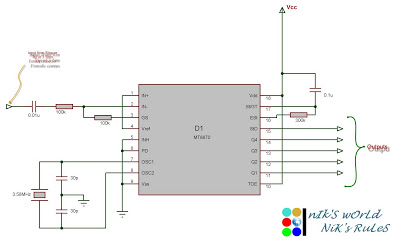
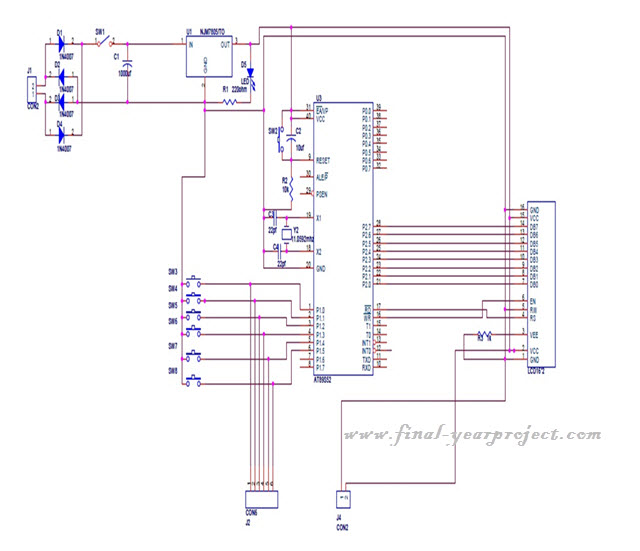
A cursory review of the HOLTEK HT640 Datasheet reveals the the TE pin on the HT640 is a CMOS input which is pulled low. This is problematic since the 8051 has outputs with a weak pullup. When the 8051 pin P3. 3 is at a `1` this will form a voltage divider and the actual level on the P3. 3/TE net will depend on the relative magnitude of the pullup and the pulldown. When P3. 3 is low all will be fine and you should get a solid low. 🔗 External reference
Related Circuits
Connect the serial cable to the serial port. If using a USB to TTL, RS232, or serial converter, plug it into the USB port. Next, short the Tx pin to the Rx pin or the TxD pin to the...
This project uses only a few of the instructions that come with PicBasic, but serves to show how easy PicBasic really is. It also shows how PicBasic strongly resembles programming the BASIC Stamp. Here we are using the serin...
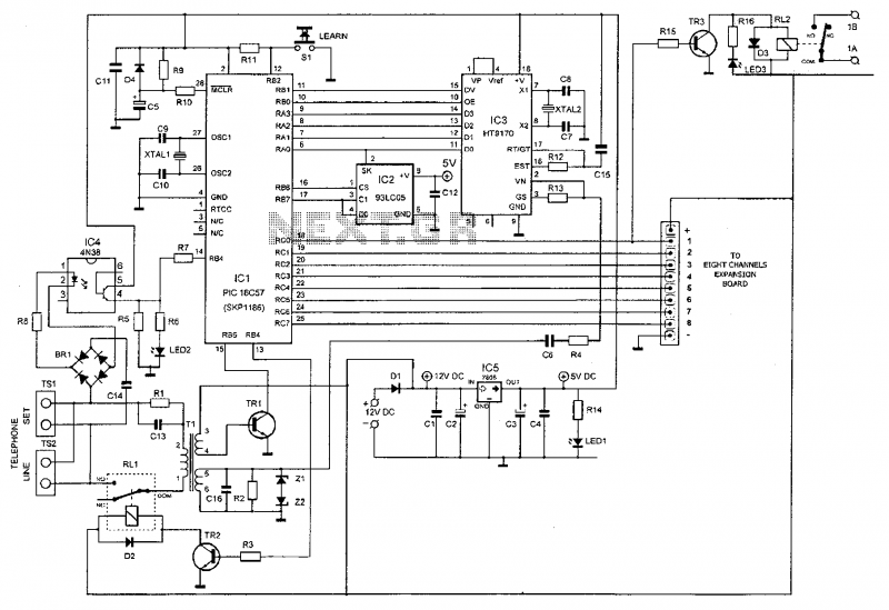
This device enables remote control of various appliances (up to eight with suitable add-on expansion boards) such as lights, water heaters, air conditioning, plant watering systems, alarms, etc., via a relay. It allows users to perform actions such as...
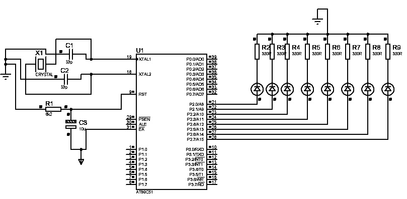
The first "Hello World!" project preferred for microcontrollers is LED blinking. An ATMEL 89C51 (40-pins DIP) microcontroller, based on the 8051 architecture, is used, which is ideal for first-time learning of MCU chips. The program is very simple and...

This article continues from the previous one regarding the single character LCD display using an AVR microcontroller. The prior article demonstrated how to display a single letter on an LCD. This article advances the learning process by explaining how...
This project is a microcontroller-based college automation system aimed at addressing the challenges faced in educational institutions. It replaces the conventional notice board with an automated device that allows users to both hear and read the information being announced...