
Dedicated headphone amplifier integrated amplifier LM4880-02

The circuit in Figure 5-41 represents a headphone amplifier utilizing the RC4558 dual operational amplifier. This integrated circuit is designed to enhance audio signals, providing improved sound quality for headphone use. The RC4558 features two independent, high-gain, internally frequency-compensated operational amplifiers, making it suitable for audio applications.
In this schematic, the input stage typically consists of a coupling capacitor that blocks any DC component from the audio source, allowing only the AC audio signal to pass through. This is crucial for preventing any potential damage to the headphones and ensuring a clean audio signal. The gain configuration is set by resistors connected to the feedback loop of the operational amplifier, allowing for customization of the amplification factor based on the desired output level.
The output stage is designed to match the impedance of typical headphones, which are usually around 32 ohms. To achieve this, the circuit may include a resistor in series with the output to help control the output impedance, thereby improving the load characteristics. Additionally, capacitors may be employed to filter out high-frequency noise, ensuring a clearer sound.
It is essential to consider power supply decoupling in this design. Bypass capacitors are typically placed close to the power supply pins of the RC4558 to stabilize the voltage and reduce noise, which can adversely affect audio quality.
Overall, this headphone amplifier circuit provides a significant improvement over directly connecting to a headphone jack, addressing the common issues of high output impedance and inadequate frequency response. By implementing this design, enthusiasts can enjoy a more satisfying listening experience with enhanced clarity and balanced audio performance.Enthusiasts know that the headphones directly into the universal headphone jack to listen to VCD, the sound quality is not high and the tape player to listen to reason D headph one amplifier is here almost all of RC4558 like amplified voltage integrated dual operational amplifier, the output impedance is high, heavy load characteristics are poor, Xin feeling harsh treble performance, the lack of a sense of bright, bass frequency response range and obviously inadequate. As required headphone output must fight Mount. Figure 5-41 circuit is one example.
Related Circuits
The following circuit diagram illustrates a simplified application circuit for the TDA8932B/33(B) device when it is powered by an asymmetrical supply (single supply). The TDA8932B/33(B) is a class-D audio amplifier integrated circuit designed for efficient audio amplification in various applications....
This amplifier is designed to be self-contained within a compact loudspeaker enclosure. It can be powered by devices such as Walkmans, Mini Discs, iPods, CD players, computers, and other devices equipped with line or headphone outputs. Typically, two units...
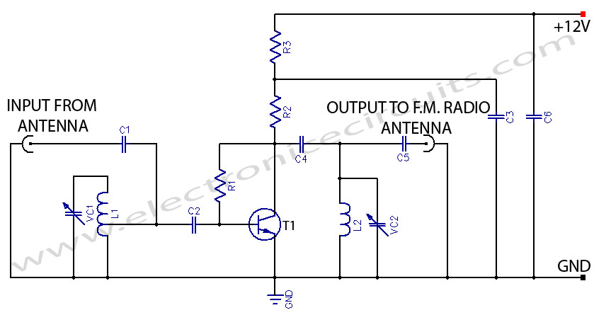
This FM booster allows for clear reception of programs from distant FM stations. The circuit features a common-emitter tuned RF preamplifier utilizing the VHF/UHF transistor 2SC2570 (only labeled as C2570 on the transistor body). The input coil L1 is...
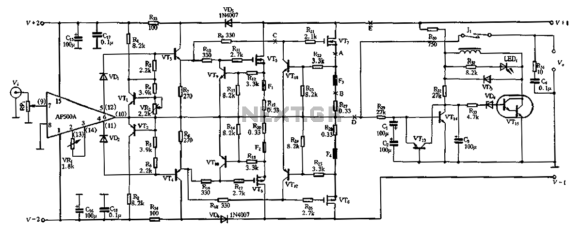
The CPI is a 100W DC super power amplifier circuit based on the AP500. It features a parallel push-pull amplifier output stage composed of transistors VT5, VT6, and VT7 to enhance output power. The circuit's output power is low...

This differential amplifier utilizes the isolated high-impedance inputs of the CA3420 BiMOS operational amplifier. The input current of the CA3240 is limited to a maximum of 50 pA, allowing for the use of 10-MΩ resistors in series with the...
This circuit functions as an RF power amplifier designed to operate with a power supply capable of delivering 13 volts at a current of 10 amperes. Careful assembly of the power source is essential. It utilizes a shielded transformer...