
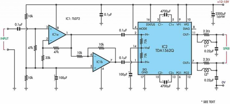
TDA8932B/33(B) Class D Audio Amplifier in Single Supply Single Ended Configuration
 Class D Audio Amplifier in Single Supply Single Ended Configuration")
The TDA8932B/33(B) is a class-D audio amplifier integrated circuit designed for efficient audio amplification in various applications. The circuit operates from a single power supply, which simplifies the design and reduces the number of components required.
In this configuration, the power supply voltage typically ranges from 10V to 30V, providing sufficient headroom for the amplifier to drive speakers effectively. The circuit includes input capacitors that block DC components while allowing audio signals to pass through. These capacitors ensure that the amplifier receives a clean audio signal without any bias voltage interference.
The TDA8932B/33(B) features built-in protection mechanisms, including thermal shutdown and short-circuit protection, which enhance the reliability of the circuit. Output filters, typically consisting of inductors and capacitors, are employed to smooth the amplified output signal, minimizing distortion and ensuring a high-quality audio output to the connected load, such as a speaker.
The feedback loop in the circuit is designed to stabilize the gain and improve linearity, contributing to the overall sound quality. Additionally, the circuit may include decoupling capacitors near the power pins of the TDA8932B/33(B) to filter out high-frequency noise and ensure stable operation.
Overall, this application circuit effectively demonstrates the capabilities of the TDA8932B/33(B) amplifier in a single-supply configuration, making it suitable for various audio amplification tasks in consumer electronics, automotive audio systems, and other applications requiring efficient audio performance.The following circuit diagram is a simplified application circuit of the TDA8932B/33(B) device when operated from an asymmetrical supply (single supply).. 🔗 External reference
Related Circuits
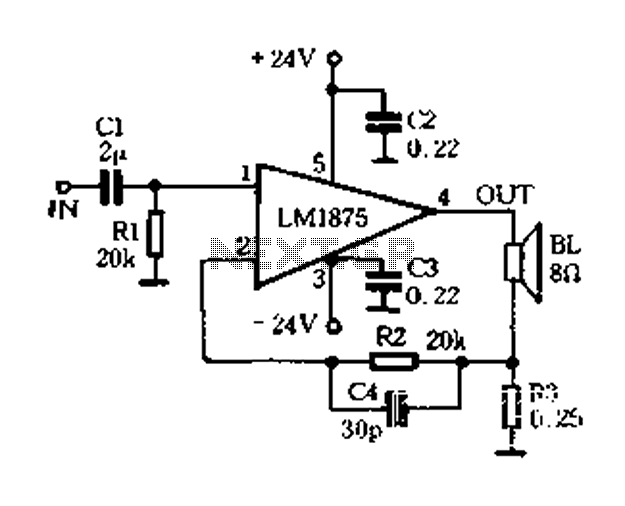
A current-sense amplifier is utilized to enhance the performance of the LM1875 current-mode amplifier circuit, as depicted in Figure 5-20. The resistor R3 and the series resistance of the speaker contribute to the current flowing through R3. This current...
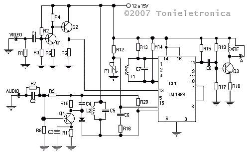
This small circuit transmitter processes audio signals from a sound table or microphone, as well as video signals from a camera, DVD, or video cassette. It has a composite video output, allowing direct transmission from a computer over a...
All the adapted numbers of the cipher are in the aforementioned line. To set the adjustment of the cardinal of the code, we accept to set the acceptable affiliation amid the bulge of the 7414 ascribe and the adapted...
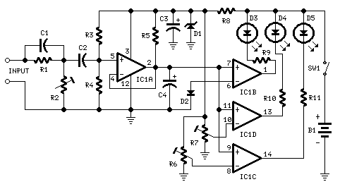
This circuit is designed to indicate the power output level of any audio amplifier. It is simple, portable, and displays three power levels that can be set to any desired value. For a standard HiFi stereo power amplifier, such...
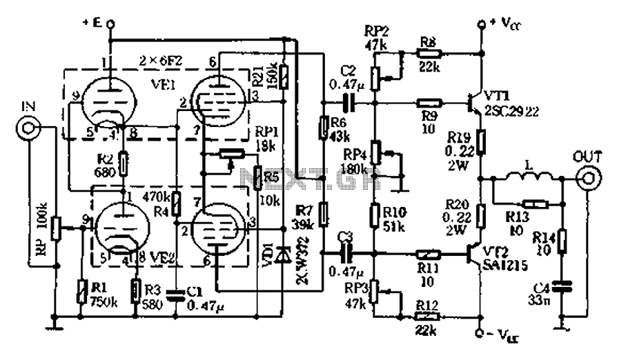
The pre-amplifier stage consists of an inverter made up of two 6F2 pentodes, with pin configurations illustrated in Figure 2.9. The electrical parameters are detailed in Table 2-3. The 6F2 tubes are well-regarded for their intensity and resolving power,...
This circuit is based on a Philips class-H audio amplifier integrated circuit (IC) and can deliver 36W RMS or 70W music power, all from a 13.8V supply. The Mighty Midget Amplifier is capable of providing approximately 36W RMS continuous...