
Delay circuit for a long time periods ( 4060 )
")
The timer circuit described utilizes the well-known 555 timer IC, which operates in astable or monostable mode to generate precise timing intervals. In scenarios where extended timing delays are required, the capacitance of the timing capacitor becomes significantly large, potentially leading to impractical component sizes. To address this, a multivibrator configuration is employed, as illustrated in the referenced Figure 1.
Upon pressing the reset button, the circuit initiates the multivibrator operation, which subsequently generates a series of output pulses. Specifically, the circuit is designed to produce 8192 pulses, equivalent to 2 raised to the power of 13. This output is derived from the counter's Q14 output, which transitions to a high state (logic level H) when the counter reaches the designated count.
The generated pulses are then routed through a diode, which serves a dual purpose: it locks the oscillator during operation and ensures that the timer remains in a waiting state for the next reset signal. This locking mechanism prevents the timer from triggering additional cycles until the reset condition is met, thereby maintaining the integrity of the timing sequence.
The operation of this timer circuit can be further understood through the accompanying timing diagram, which illustrates the relationship between the input reset signal, the multivibrator output, and the counter states. The timing diagram aids in visualizing the pulse generation and the subsequent locking of the oscillator, providing a comprehensive overview of the circuit's functionality.If you need a timer circuit, we go after the most proven 555th However, if the delays are longer, based on timing capacitor capacity is too large. In this case, a circuit of Figure 1 After pressing the button - reset circuit - starts multivibrator.
It vibrates so long to fill the output Q14 of the counter and moves to the level of H. multivibrator to produce pulses 8192 (2 13 ). Through the diode is then locked oscillator and a timer waiting for the next reset. Everything is clear from the timing diagram. 🔗 External reference
Related Circuits
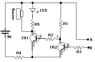
This document presents a water sensor circuit designed to monitor soil moisture levels for plants. This circuit is straightforward and is constructed using five resistors, two transistors, an LED, a buzzer, and a battery. The operation of the circuit...
The sections available in this datasheet cover general design considerations for the 555 timer, frequently asked application questions (FAQ), design formulas, and examples of innovative applications. Examples of applications include a Missing Pulse Detector, Pulse Width Modulation (PWM), Tone...
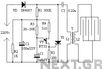
The electronic fly disinfestation system is a simple and effective device designed to eliminate flies using electrical means. The apparatus, as depicted in Figure 1, operates on 220V mains power supplied directly through a rectifier. It utilizes a relaxation...
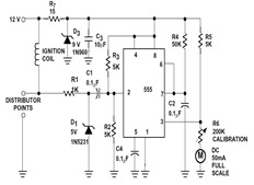
This circuit can detect whether a train is in a particular drive. The output is TTL and CMOS compatible and can be processed by such a computer. The simple circuit works. The driving voltage is connected to the two...
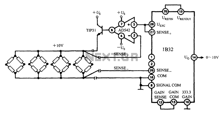
The 1B32 application circuit features multiple pressure sensors as illustrated in the figure. Excitation power is supplied through the AD542, which is followed by a TIP32 transistor that drives multiple bridge sensors. The AD542 operates as a Bi-FET in...
The circuit consists of a series of dual power supplies, providing a symmetrical ±15V supply for linear circuits. The same principle is applicable to non-symmetrical supplies, such as 5.0V and -12V regulators, which are used in applications like registers....