
dual power supply circuit

The dual power supply circuit is designed to deliver stable voltage outputs suitable for various linear applications. The symmetrical outputs of ±15V are achieved using a combination of voltage regulators and diodes to ensure reliability and protection against faults. The LM340 voltage regulator is the primary component, known for its ability to maintain a steady output voltage despite variations in load and input voltage.
In this circuit, the addition of the germanium diode D1 is crucial. Its lower forward voltage drop compared to the silicon diode ensures that it can effectively divert excess fault currents, thereby protecting the LM340 from potential damage during startup and under load conditions. This feature is particularly important in scenarios where the load might present a negative voltage, as it allows the LM340 to function correctly without being adversely affected.
Furthermore, the circuit incorporates silicon diode D2, which serves a dual purpose: it protects against shorts to ground and between the outputs of the regulators. This is essential for maintaining the integrity of the power supply, as shorts can lead to severe damage or failure of the regulators. The design ensures that in the event of an output short, the voltage difference between the inputs and the opposite regulator output remains within safe limits, adhering to the maximum ratings specified for the components.
In summary, this dual power supply circuit is meticulously designed to offer reliable ±15V and non-symmetrical voltage outputs while incorporating protective measures to safeguard against common electrical faults. The use of both germanium and silicon diodes enhances the robustness of the circuit, ensuring stable operation across a range of conditions.The circuit a series of Dual Power Supply, where the symmetrical ± 15V supply for linear circuits. The same principle applies to supplies of non-symmetrical, such as 5. 0 V and-12V regulators for applications such as registers. To ensure start up LM340 over full temperature range of the load sink current worst case 1. 0a germanium power diode D1 was added to the circuit. Since the forward voltage drop of the germanium diode D1 is less than that of the silicon substrate diode of the LM340 the external diode will take any fault current and allow the LM340 to start up even into a negative voltage load. D1 and silicon diode D2 also protect the regulator outputs from in advertent shorts between outputs and to ground.
For shorts between outputs the voltage difference between either input and the opposite regulator output should not exceed the maximum rating of the device. Here is a schematic drawing: 🔗 External reference
Related Circuits
This circuit is designed to indicate the power output level of any audio amplifier. It is simple, portable, and displays three power levels that can be adjusted to any desired value. The circuit operates by measuring the output voltage from...
During experiments with various receivers and amplifiers powered by "free energy," it was discovered that connecting the audio amplifier to the receiver using only two wires for audio signals and supply voltage is more convenient. This setup allows the...
The tester provides an audible indication of the logic level of the signal presented to its input. A logic high is indicated by a high tone, a logic low is indicated by a low tone, and oscillation is indicated...
This document contains a collection of schematic diagrams, datasheets, images, and tips for switch mode power supplies (SMPS) utilizing the TL494, LM339, KA7500, and IC2003 integrated circuits. Switch Mode Power Supplies (SMPS) are crucial components in modern electronic devices, providing...
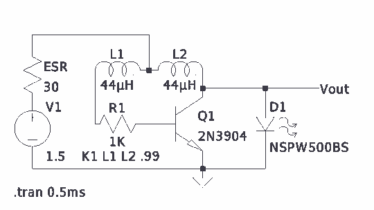
There is much pleasure in useless knowledge. The value of the inductors (44 µH) was determined using an online toroid calculator, specifying an FT-50-43 toroid with 10 turns through it. The described circuit involves the use of an FT-50-43 toroidal...
A device that conducts electric current and converts electrical energy into another form. Power consumed by a device or circuit while performing its function can be represented by a resistor and capacitor. The capacitor in the load circuit represents...