
Delay circuit with LM339

The circuit utilizes an LM339, a quad comparator that allows for multiple voltage comparisons, enhancing the design's efficiency. The first three comparators are configured in parallel to amplify the control signal, effectively driving a PNP transistor (2N2905), which is capable of handling moderate power levels. This PNP transistor functions as a switch, allowing the high current NPN transistor (TIP35) to be activated. The TIP35 is essential for managing the high current output, rated for up to 15 amps, making it suitable for applications requiring substantial power.
The fourth comparator is critical for implementing the time delay feature. It monitors the state of a normally closed switch. When the switch is opened, the comparator initiates a timing sequence determined by an RC (resistor-capacitor) network. The voltage divider formed by the 36K and 62K resistors ensures that the input to the comparator remains stable, providing a reference voltage of approximately 2 volts, which is essential for accurate timing.
The timing mechanism relies on a 50uF capacitor in combination with a variable resistor set at 100K. This configuration results in a time constant of approximately 5 seconds, calculated using the formula τ = R × C. Adjusting the variable resistor or capacitor allows for fine-tuning of the delay duration. For shorter delays, decreasing the resistance or capacitance is recommended, while longer delays can be achieved by increasing either parameter.
To accommodate different operating voltages, the circuit includes a provision to adjust the 10-ohm resistor. For higher voltage applications, the resistor value should be increased proportionally to maintain circuit stability and performance. This adaptability makes the circuit versatile across various battery voltages, ensuring reliable operation under different conditions. Overall, this design exemplifies an efficient method for controlling high current loads with a timed delay, utilizing readily available components.In this circuit a LM339 quad voltage comparator is used to generate a time delay and control a high current output at low voltage. Approximatey 5 amps of current can be obtained using a couple fresh alkaline D batteries. Three of the comparators are wired in parallel to drive a medium power PNP transistor (2N2905 or similar) which in turn drives a high current NPN transistor (TIP35 or similar).
The 4th comparator is used to generate a time delay after the normally closed switch is opened. Two resistors (36K and 62K) are used as a voltage divider which applies about two-thirds of the battery voltage to the (+) comparator input, or about 2 volts. The delay time after the switch is opened will be around one time constant using a 50uF capacitor and 100K variable resistor, or about (50u * 100K) = 5 seconds.
The time can be reduced by adjusting the resistor to a lower value or using a smaller capacitor. Longer times can be obtained with a larger resistor or capacitor. To operate the circuit on higher voltages, the 10 ohm resistor should be increased proportionally, (4.5 volts = 15 ohms). 🔗 External reference
Related Circuits
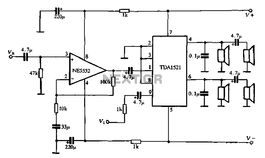
Active speaker with amplifier circuit TDA1521 and NE5532, featuring dual-channel input and dual-channel output. The active speaker circuit utilizes the TDA1521 integrated circuit, which serves as the power amplifier. This IC is designed for high-efficiency amplification, providing a robust output suitable...
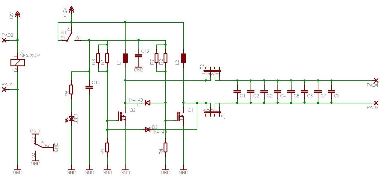
Instructions to assemble a small project on wireless energy transfer. If anyone has a simple schematic suitable for beginners, please share or provide instructions. The simplest one found so far is from a Hungarian YouTube channel, but it is...

The input capacitor is used for low-frequency cut-off, with a standard value of 0.1 µF, resulting in a cut-off frequency of approximately 16 Hz. The input capacitor plays a critical role in electronic circuits, particularly in signal processing and audio...
A voltage supply ranging from 6 V to 15 V is required when using a single LED per module. An increase in the number of LEDs necessitates a corresponding increase in the voltage supply, with additional LEDs connected in...
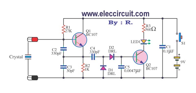
A multimeter cannot be used to test a crystal oscillator. Instead, a dedicated circuit is required, capable of checking crystals within the frequency range of 100 kHz to 900 MHz. This circuit is easy to construct and cost-effective. To construct...
There are two differing opinions regarding the charging of alkaline batteries. Some assert that charging is effective, while others caution against it due to the risk of explosion. It is acknowledged that rechargeable alkaline batteries can typically endure 30...