
Delay Switch

The connections of the switch are also simple. The indicated connections on the track with the switch connected. In the broken piece of the train, it will slow down and wait. At H0, this piece is about 1 meter, and at 0.5 N m. Of course, this also depends on the length of the train. When the circuit is connected as shown, the train will stop in one direction only. To allow the train to stop in both directions, a bridge rectifier should be mounted between the rail terminals and the circuit with the AC terminals on the rails, plus the 'rails' terminal and ground to the 'output' connection. A switch can also be installed on the two terminals of the switch. When the switch is closed, the train stops and does not just drive by. A final transistor T3 requires a small heat sink to be mounted. The switch can then handle a current of up to 2 A.
R1 = 150 kOhm
R2 = 22 kOhm
R3 = 0.22 Ω / 2 W
R4 = 1 kOhm
P1 = 100 kOhm
P2 = 10 kΩ
C1 = 220 V µF/16
C2, C3 = 47 µF/16 V
T1, D2 = 1N4002
T1, T4 = 547 BC
T2 = 517 BC
T3 = BD 433
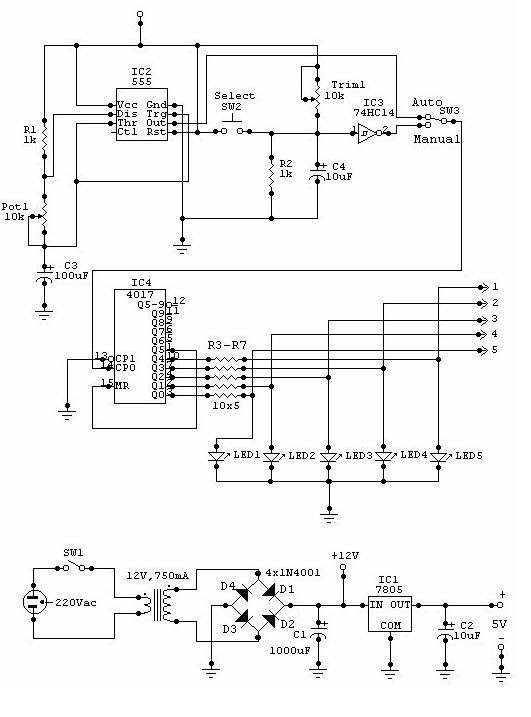
The described circuit functions as a control mechanism for model trains, particularly at stations where a stop-and-go operation is desired. The use of two potentiometers (P1 and P2) allows for user-defined adjustments of waiting time and acceleration rates, enhancing the flexibility of the system. P1 adjusts the duration the train remains stationary, with the ability to fine-tune this based on operational requirements. P2 governs the rate of acceleration and deceleration, allowing for a more realistic train operation.
The circuit utilizes a combination of resistors (R1, R2, R3, R4) to set appropriate biasing levels and current limits for the transistors (T1, T2, T3, T4), which act as switches to control the flow of current to the train's motor. The inclusion of capacitors (C1, C2, C3) serves to filter voltage spikes and stabilize the power supply, ensuring smooth operation of the circuit.
In terms of connectivity, the circuit is designed to be straightforward, allowing for easy integration with existing model train setups. The suggestion to use a bridge rectifier for bi-directional operation indicates a level of sophistication in the design, accommodating trains that may need to reverse direction without requiring manual intervention.
The specifications for the components suggest a robust design capable of handling the electrical demands of model train operation, particularly with the transistor T3 rated for a current of up to 2 A, making it suitable for most model train motors. The heat sink requirement for T3 further indicates that the circuit is designed to dissipate heat effectively, ensuring reliability during extended use.
Overall, this circuit provides a practical solution for automating model train operations at stations, enhancing user experience through adjustable parameters and reliable performance.This switch allows the model train at such a station will automatically slow down. The train stands for a certain amount of time and then slowly pulls back. You do not own the train to stop. The relatively simple circuit works. P1 potentiometer for setting the waiting time, while turning to A caused a shorter waiting time and turn to B results in a longer waiting period. P2 is to set the brake and acceleratieweg. Here, too, turn to A results in faster acceleration and the train slows. The connections of the switch are also simple (see picture connections). The indicated connections on track with the switch connected. In the broken piece of the train will slow down and wait. At H0, this piece is about 1 meter to be, and at 0.5 N m. Of course this also depends on the length of the train. When the circuit is connected as shown, the train will stop in one direction only. Want to train in both directions to stop, then mount a bridge rectifier between the rail terminals and the circuit with the AC terminals on the rails, plus the 'rails' terminal and ground to the' uitgang' connection. You can also stop off. Install a switch on the two terminals of the switch. When the switch is closed, the train stops and not just drive by. Final Transistor T3 is a small heat sink to be screwed. The switch can then flow up to 2 A. R1 = 150 kOhm R2 = 22 kOhm R3 = 0.22 ? / 2 W R4 = 1 kOhm P1 = 100 kOhm P2 = 10kW C1 = 220 V ?F/16 C2, C3 = 47 ?F/16 V T1, D2 = 1N4002 T1, T4 = 547 BC T2 = 517 BC T3 = BD 433
🔗 External reference
Related Circuits
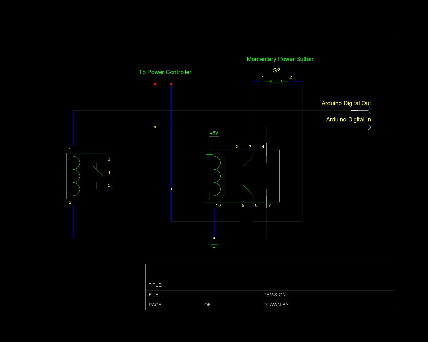
The power controller module in the system receives input directly from a momentary switch and utilizes this input to toggle a relay, which supplies mains power to the system's transformers. The controller circuit operates at 12V, a choice made...
This is a power-on time delay relay circuit that utilizes the emitter/base breakdown voltage of a standard bipolar transistor. The reverse-connected emitter/base junction of a 2N3904 transistor functions as an 8-volt zener diode, establishing a higher turn-on voltage for...
This circuit can be utilized for multiple cameras with a single monitor. The operation can be manual or automatic. In automatic mode, the switch... This circuit is designed to enable the connection of multiple cameras to a single monitor, allowing...
This compact switching power supply utilizes a Schmitt trigger oscillator to control a switching transistor, which provides current to a small inductor. When the transistor is activated, energy accumulates in the inductor, and this energy is subsequently released into...
The two circuits below illustrate opening a relay contact a short time after the ignition or light switch is turned off. The capacitor is charged and the relay is closed when the voltage at the diode anode rises to...
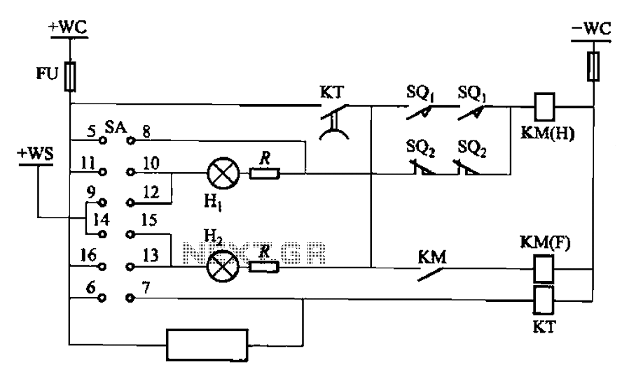
The BT9404 is a de-excitation type switch utilized with CJ4-S contactors and JT3-21/3-type electromagnetic relays. The control circuit is depicted in Figure 7-55. The KM contactors used are CJ4-S, while the time relay is the JT3-21/3. The SA component...