
Power Off Delay Relay circuits

The described circuits are designed to control a relay's operation based on the ignition or light switch status. The first circuit, utilizing a common collector configuration, simplifies the design by eliminating the need for a series resistor with the transistor base. However, this results in a reduced voltage across the relay coil due to the inherent voltage drop across the diodes. Specifically, with a supply voltage of 12.5 volts, the relay coil receives approximately 11 volts, which may affect its performance during operation.
In contrast, the second circuit employs a common emitter configuration, which allows for the full supply voltage to be applied across the relay coil for the majority of the delay period. This configuration enhances the reliability of the relay's operation, as it mitigates concerns regarding pull-in and drop-out voltage levels. The inclusion of a series resistor with the transistor base enables the user to fine-tune the delay time by adjusting the resistor value, offering flexibility in design.
The time delay for the common emitter circuit can be calculated using the formula for time constants, expressed as 3 times the product of the resistance (R) and capacitance (C). For practical implementation, the relay coil specifications and the transistor's current gain are crucial parameters in determining the appropriate resistor and capacitor values. For instance, with a relay coil resistance of 120 ohms drawing 100 mA at 12 volts, and assuming a transistor gain of 30, the required base current is calculated to be 3 mA. Consequently, the voltage across the base resistor is derived from the supply voltage minus the voltage drop across the diodes, yielding approximately 10.6 volts. This leads to the calculation of the resistor value at approximately 3.6K ohms.
To achieve a desired delay of 15 seconds, the capacitor value can be computed using the time constant formula. The calculations indicate a need for a capacitor of approximately 1327 microfarads. A standard capacitor of 1000 microfarads can be utilized, with a proportional increase in the resistor value to meet the delay requirement. This setup ensures that the relay operates effectively within the specified time frame, providing a reliable solution for controlling the relay based on the ignition or light switch status.The two circuits below illustrate opening a relay contact a short time after the ignition or ligh switch is turned off. The capacitor is charged and the relay is closed when the voltage at the diode anode rises to +12 volts.
The circuit on the left is a common collector or emitter follower and has the advantage of one less part since a resistor is not needed in series with the transistor base. However the voltage across the relay coil will be two diode drops less than the supply voltage, or about 11 volts for a 12.5 volt input.
The common emitter configuration on the right offers the advantage of the full supply voltage across the load for most of the delay time, which makes the relay pull-in and drop-out voltages less of a concern but requires an extra resistor in series with transistor base. The common emitter (circuit on the right) is the better circuit since the series base resistor can be selected to obtain the desired delay time whereas the capacitor must be selected for the common collector (or an additional resistor used in parallel with the capacitor).
The time delay for the common emitter will be approximately 3 time constants or 3*R*C. The capacitor/resistor values can be worked out from the relay coil current and transistor gain. For example a 120 ohm relay coil will draw 100 mA at 12 volts and assumming a transistor gain of 30, the base current will be 100/30 = 3 mA. The voltage across the resistor will be the supply voltage minus two diode drops or 12-1.4 = 10.6. The resistor value will be the voltage/current = 10.6/0.003 = 3533 or about 3.6K. The capacitor value for a 15 second delay will be 15/3R = 1327 uF. We can use a standard 1000 uF capacitor and increase the resistor proportionally to get 15 seconds. 🔗 External reference
Related Circuits
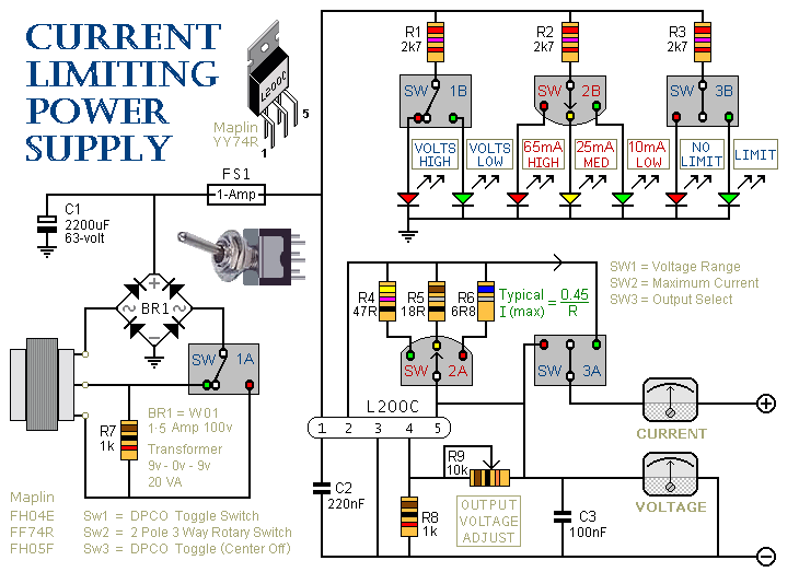
This is a 1-amp variable-voltage power supply unit (PSU) that adjusts the output voltage from approximately 3V to 24V. It features a current limiting option, which is particularly useful for initial power-ups or soak-testing equipment. SW3 acts as the...
A used 250VA power transformer has been removed from equipment recently. The transformer features a dual 10V AC output along with several auxiliary voltage outputs. The 10V winding is rated for 10A, making it suitable for a high current...
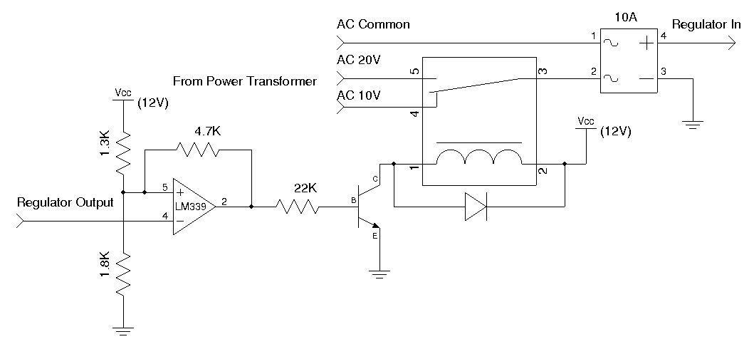
The circuit requires a double pole, double throw relay in conjunction with a single transistor to allow toggling the relay with a momentary push button. One set of relay contacts is used to control the load, while the other...
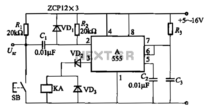
The 555 integrated circuit is utilized in a delay circuit configuration, functioning as a one-shot timer. The delay time can be adjusted using resistor R3 and capacitor C3. Typical values for R3 range from 1 kΩ to 10 MΩ,...
The output current range of the parameter current regulator is limited, and its precision is not high. Connecting the feedback adjustment type output current of the current-stabilized power source in series results in lower efficiency. The steady current source...
The simple relay adder was constructed using free NOS relays around 2005, with the intention of eventually creating a more complex version capable of running programs without occupying a large space like early computers. An impressive 415-relay computer was...