
Delayed pulse generator

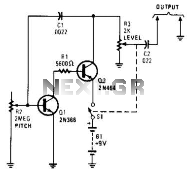
The resistor R2 and capacitor Cl values determine the initial delay, while resistor R3 and capacitor C2 set the pulse rate. The specified component values will yield a delay of approximately 0.5 seconds and a pulse rate of 200 to 300 Hz, depending on the supply voltage. PB1 can be substituted with an open collector TTL gate or a common emitter transistor stage if necessary.
This circuit is designed to provide a flexible timing solution where both the initial delay and pulse frequency can be adjusted through the selection of appropriate resistor and capacitor values. The use of a pulse generator allows for the generation of high-frequency signals, which can be useful in various applications such as signal modulation, timing circuits, or as a control signal for other electronic devices.
The charging and discharging of capacitor Cl through resistors R2 and R1, respectively, define the timing characteristics of the circuit. The rapid discharge through diode D1 ensures that the capacitor returns to a low state quickly, allowing for a precise timing sequence. The choice of components, including the specific values of R2, R3, C1, and C2, will directly influence the performance and response time of the circuit, making it essential to select components based on the desired application requirements.
In practical applications, the circuit can be integrated into larger systems where timed signals are necessary, such as in automated control systems, timers, or pulse-width modulation applications. The option to replace PB1 with a TTL gate or transistor stage enhances the circuit's versatility, allowing for integration with digital logic systems or more robust switching mechanisms. Overall, this circuit exemplifies a straightforward yet effective approach to generating timed pulse outputs in electronic designs.The circuit offers independent control of initial delay and pulse rate. ICIc is connected as a pulse generator whose operation is inhibited by the normally low O/P of the ICla. When the circuit input goes low i.e., by pressing PB1, IClb O/P goes high and the circuit O/P goes low thus replicating the input.
When the input is kept low capacitor Cl charges via R2 to a point where ICla O/P goes low. This allows the pulse generator ICIc to start and "rapid fire" pulses appear at the circuit O/P. When the circuit input returns to the high state Cl is rapidly discharged viaD1 and Rl. The value of R2 and Cl control the initial delay while R3 and C2 control the pulse rate. The values given will give a delay of around 0.5 seconds and a pulse rate of 200/300 Hz depending on supply voltage. PB1 may be replaced by an open collector TTL gate or a common emitter transistor stage if required.
Related Circuits
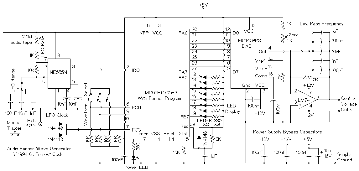
This device is a microprocessor controlled waveform generator that can be used for driving a voltage controlled stereo panner for music applications. Panning is simply the movement of a mono audio signal between the left and right channels of...
A high-quality tone burst generator can be constructed using a 556 Dual Timer. The first half of the timer can be configured as a one-shot, while the second half can function as an oscillator. The 556 Dual Timer is an...
Useful for troubleshooting audio, video, and lower frequency RF amplifiers. This circuit generates a signal that is rich in harmonics. The circuit designed for troubleshooting audio, video, and lower frequency RF amplifiers is crucial for diagnosing issues in these systems....
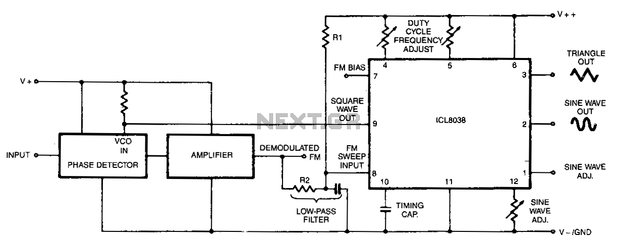
In this circuit, a waveform generator is used as a stable voltage-controlled oscillator (VCO) in a Phase-Locked Loop (PLL). The circuit utilizes a waveform generator configured as a voltage-controlled oscillator (VCO), which is a critical component in the design of...
There are various methods to create pedal generators, utilizing different components such as bicycle parts or exercise bikes as a foundation. Each approach has its advantages and disadvantages, but for individuals who have not constructed one before and wish...
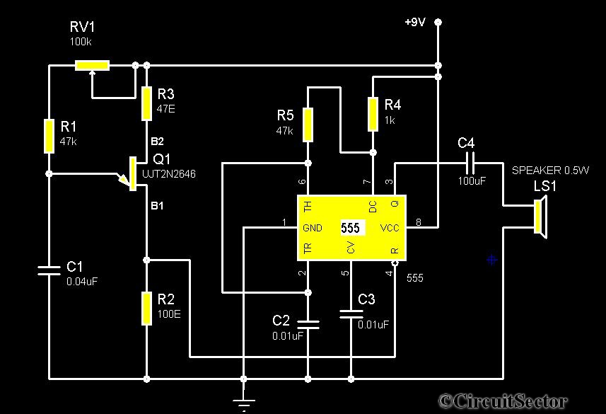
The circuit diagram illustrates a timer 555-based rain sound generator. It requires a 9V DC power supply, which can be provided by a 9V battery. The circuit utilizes a 0.5W, 8-ohm speaker to produce sound. When powered by a...